IMPORTANT
Flat edge of washers (O) must be against drive shaft.
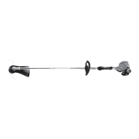
install shield and gear case assembly
1. Install gear case assembly on end of drive shaft taking care to
engage the drive cable with the gear case.
2. Align the gear case on the drive shaft and install the locating
screw (N).
3. Tighten the two (2) side clamping screws (M).
blade conversion kit installation instructions
4
install plastic blade shield
Tools Required: Torx T27 L-Wrench
Parts Required: Wide Plastic Shield, Shield Plate,
• 3 - 5 x 25 mm screws, (plastic shield to gear
case).
• 3 - 5 mm lock nuts
1. If installed remove nylon line head, upper xing plate, shield plate,
and plastic shield.
a. Align locking hole in upper plate with notch in edge of gear
housing and insert head locking tool (A).
b. Remove line head (B) by turning it clockwise until head is
completely off of shaft.
c. Remove locking tool.
d. Remove three screws holding shield plate and plastic shield
(C) to gear case.
e. Retain all parts for conversion back to nylon line head operation.
A
C
B
M
M
N
O
O
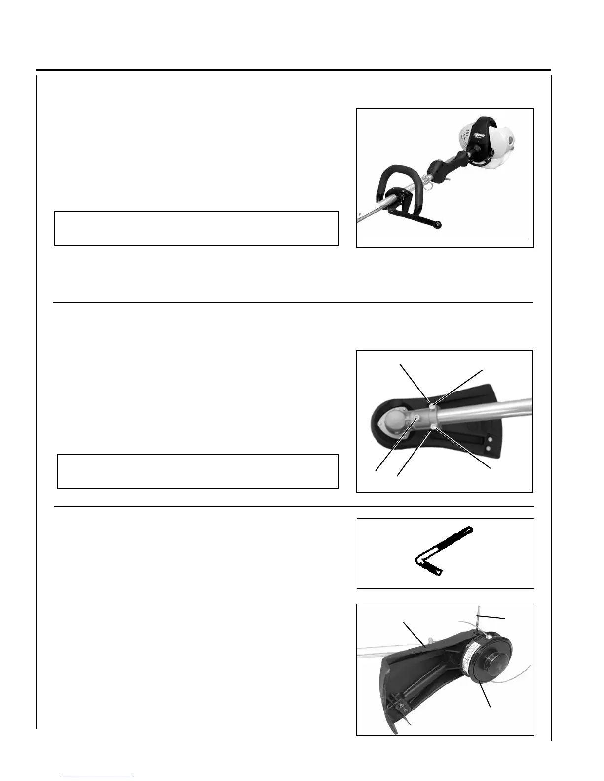
SRM’s with 2-screw front handles
1. Position front handle on shaft and install Barrier Bar using two
(2) 5x35 mm screws provided in kit. Handle must be at least 10
inches (250 mm) from center of rear handle grip.
2. Adjust handle position for comfortable operation, and tighten
screws securely.
NOTE
The Barrier Bar is not a handle.