17
IGNITION SYSTEM
CS-370ES
CS-420ES
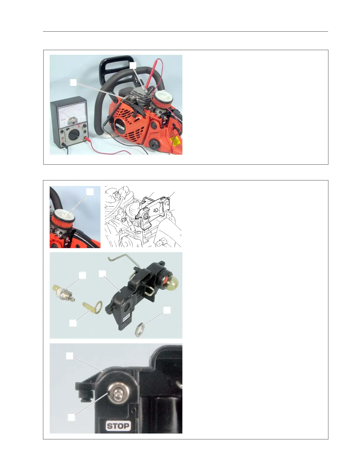
3-4 Inspecting ignition switch
1. Remove cylinder cover.
2. Connect one probe of Ohm-meter or multi-meter
to primary lead (A) and the other probe to cylinder
fin.
3. When ignition switch is in “RUN” position, tester
should indicate infinite resistance.
4. When ignition switch is in “STOP” position, tester
should show that the circuit is in conducting state
(closed circuit).
5. If ignition switch is defective, replace with a new
one.
3-5 Replacing ignition switch
1. Remove air cleaner bracket (G) and air filter.
Disconnect primary lead and ground lead from
ignition switch.
2. Disconnect throttle rod (B) from carburetor (Refer
to “9-4 Replacing throttle trigger”) and remove switch
bracket (A) from engine cover.
3. Loosen nut (C), and remove ignition switch (D)
and switch plate (E) from switch bracket (A).
4. Inspect switch plate (E) and switch bracket (A).
If damaged, replace with new parts.
5. Align notch (F) of new ignition switch with tabs of
switch plate (E) and switch bracket (A). Fasten nut
(C) on ignition switch.
6. Connect throttle rod to carburetor.
7. Put switch bracket (A) into engine cover correctly.
Connect primary lead and ground lead to ignition
switch.
A
B
BA
C
D
C
A
E
F
A
G
D