12
ASSEMBLY
PLASTIC
SHIELD INSTALLATION
Tools Required: Screwdriver, Locking Tool
Parts Required: Plastic Debris Shield, Shield Plate,
three (3) 5 x 16 mm screws.
WARNING DANGER
The plastic shield is for use with the Nylon Line Head only. Install
Metal Shield when using plastic or metal blades, or serious injury
may result.
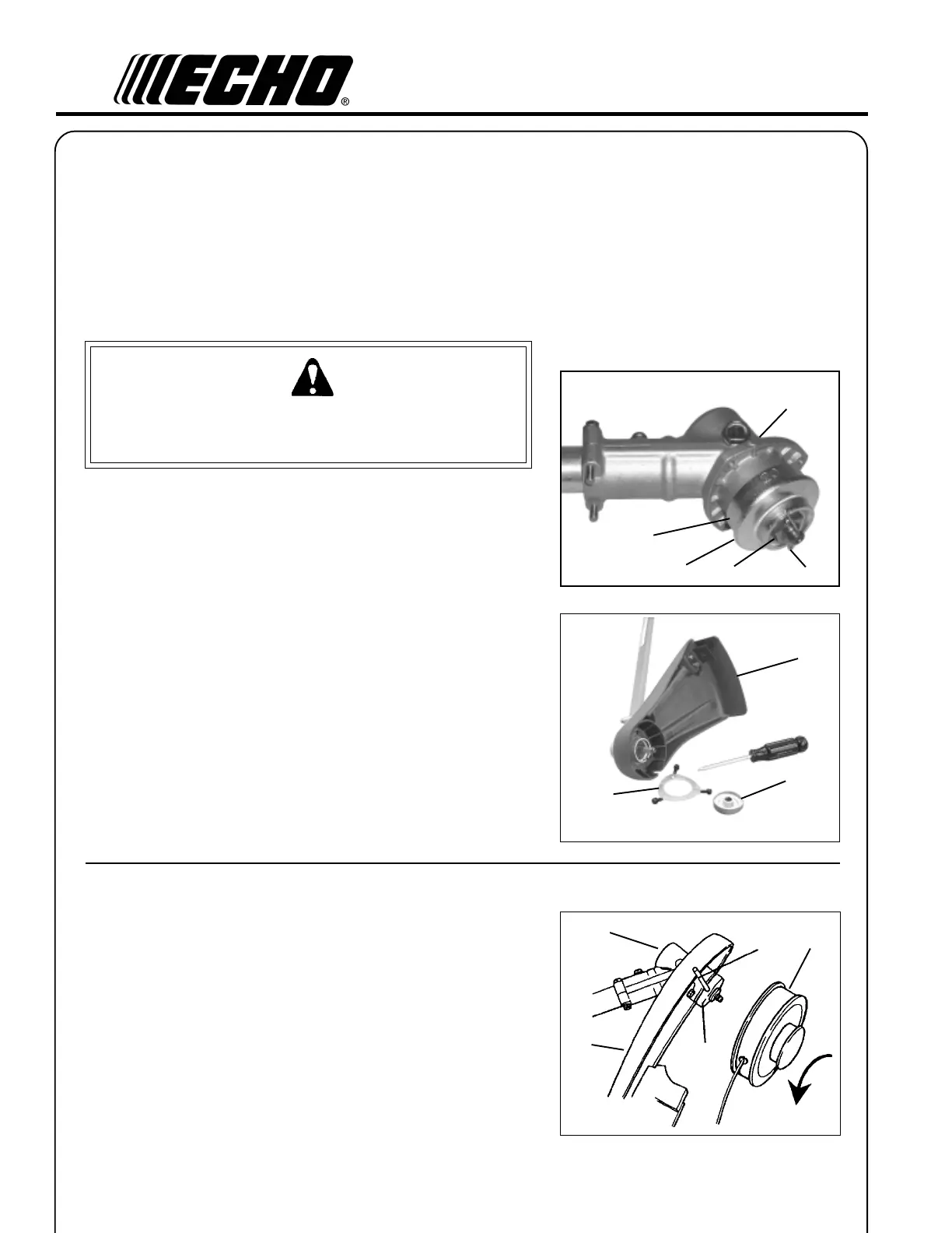
1. Align hole in upper plate (D) with notch in gear housing (G), and
insert locking tool to prevent splined shaft from turning. Arrow on
gear housing flange points to notch location.
2. Remove cotter pin (A), L.H. blade nut (B), lower plate (C), and
upper plate (D) from PTO shaft. Turn blade nut clockwise to
remove.
3. Remove locking tool. Retain lower plate, blade nut, and cotter pin
for future use with blade conversions.
4. Align plastic debris shield (F) with the drive shaft, and install on
the bottom of the gear housing flange.
5. Place shield plate (E) on shield, align holes and install three (3)
screws.
6. Replace upper plate (D) on PTO shaft.
NYLON HEAD INSTALLATION
Tools Required: Locking Tool, 17x19 mm Scrench
Parts Required: Nylon Line Head.
1. Make sure plastic debris shield (F) is properly aligned, and upper
plate (D) is installed on splined PTO shaft.
2. Align hole in upper plate (D) with notch in gear housing (G), and
insert locking tool (H) to prevent splined shaft from turning.
3. Thread line head (I) onto PTO shaft by turning it counter-clock-
wise until head is tight against upper plate (D).
4. Remove locking tool.
E
D
F
C
B
A
D
G
H
D
G
F
I