10
ASSEMBLY
Tools Required: Screwdriver, Head Locking Tool, 17x19mm T-Wrench
Parts Required: Plastic Shield, Shield Plate, three (3) 5mm x 16mm
screws, Nylon Line Head
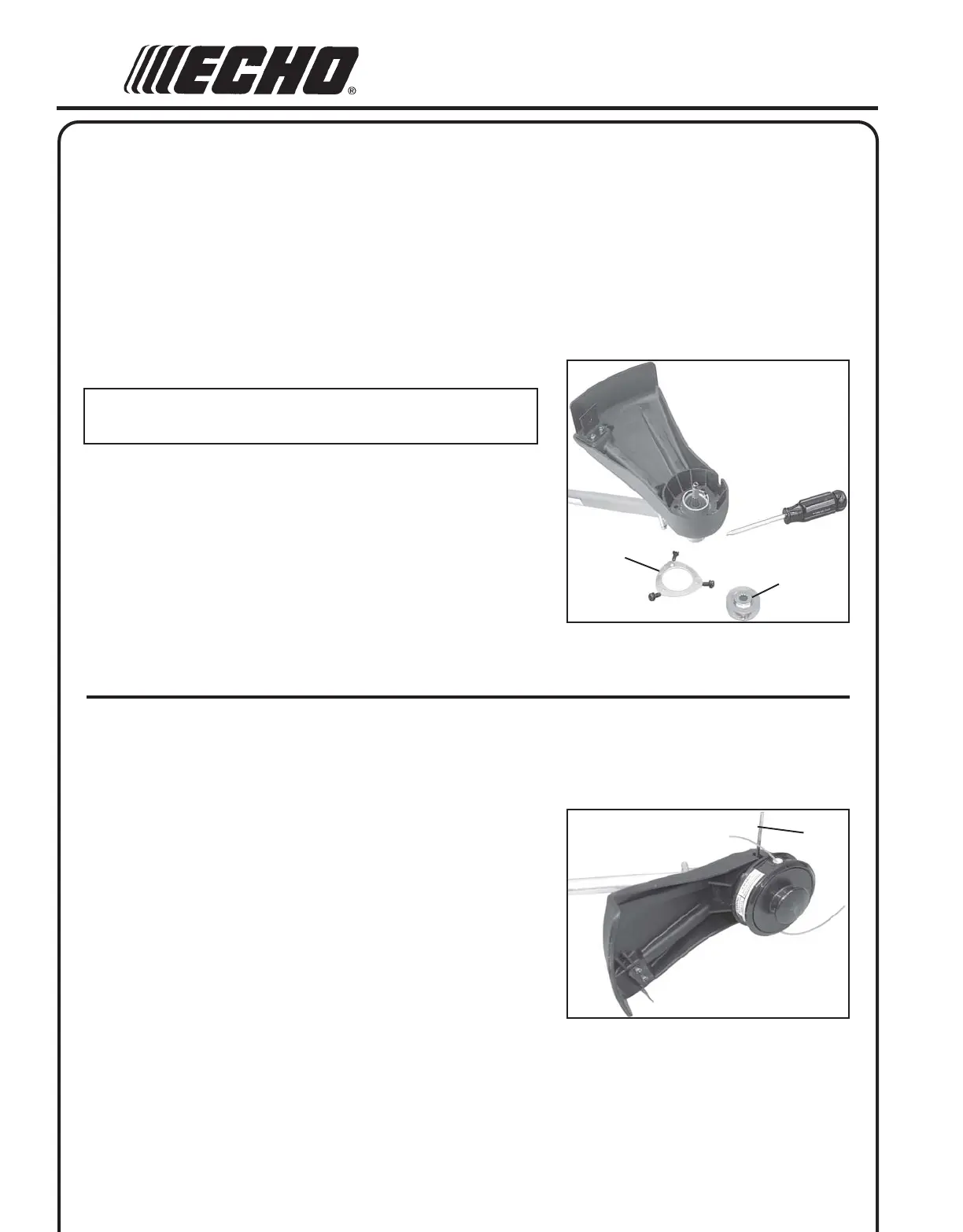
PLASTIC SHIELD INSTALLATION
(For Nylon Line Operation)
NOTE
The plastic shield is for use with the Nylon Line Head only.
1. Remove plastic sleeve and upper plate (A) from PTO shaft.
2. Install the shield on the bottom of the bearing housing flange.
3. Place shield plate (B) on shield, align holes and install three (3)
5x16 mm screws.
4. Install upper plate (A).
B
A
C
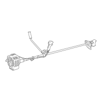
NYLON LINE HEAD INSTALLATION
1. Align hole in upper plate with notch in edge of gear housing and
insert head locking tool (C). Remove plastic sleevefrom PTO shaft.
2. Be sure upper plate (A) remains on PTO shaft.
3. Thread line head onto PTO shaft by turning it counter clockwise
until head is tight against upper plate.
4. Remove locking tool (C).