9
Table 1: Torque Values
Location
Torque Value
(ft-lbs unless
otherwise noted)
Pivot bolt (Mast foot; ensure no mast deformation occurs
during tightening)
4.5
Mast adjustment bolts 12
Reectormountingbolts 8
Mast bolts 12
Elevation bolts 12
Elevation rod nuts Handtight
Azimuthbolts(donottightenazimuthne-tunecam) 12
Skew bolts 12
LNBF support to elevation and skew bracket bolts 4
LNBF support to 129 LNBF bracket bolts 2
LNBF and LNBF bracket attachment hardware 2
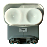
Fine-tune the azimuth angle. For the DISH Pro 500+ (Dual Band) LNBF, move the
temporary peaking cable from Port 2D to Port 1F. For the DISH Pro Plus 500+ LNBF and if
using a meter that is not capable of selecting orbits, move the tempoarary peaking cable to
Port 3. For the DISH Pro Plus 500+ LNBF and if using a meter that is capable of selecting orbits,
continuetothenextsentence.Withthepeakingmeterstillconnected,ne-tunetheazimuthangle
(see Figure 8). Loosen the three azimuth bolts enough so that the two azimuth plates can rotate.
Usinga1/2”wrench,rotatetheazimuthne-tunecamtoadjusttheazimuthangletoachieve
maximum signal, using the 118.7°W satellite and transponder 13. After obtaining maximum
signal, tighten the three azimuth bolts labeled with a T to the recommended torque value given in
Table 1 on page 9. Do not torque the azimuth ne-tuning cam.
Note:Youcanadjusttheazimuthanglethreedegreesineitherdirectionusingtheazimuthne-
tune cam. If the azimuth angle needs to be adjusted more than three degrees, loosen the mast bolts
to make the adjustment.
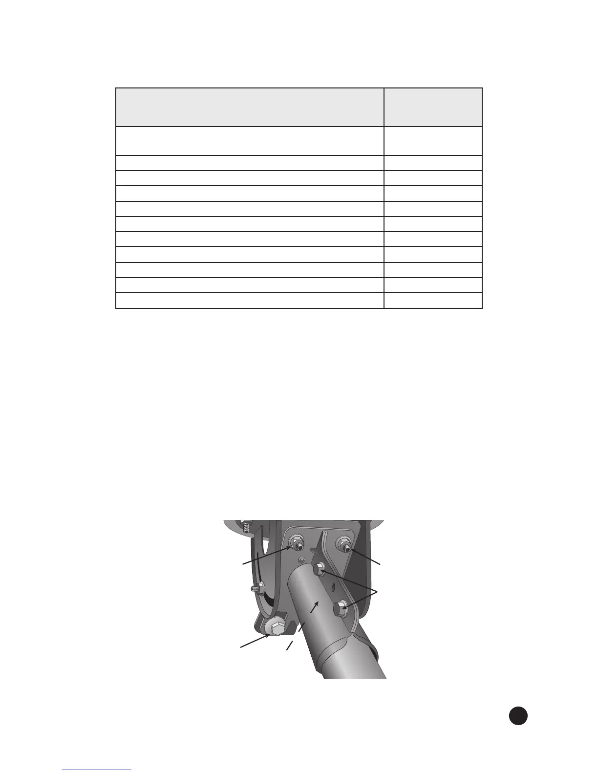
Figure 8. Fine tuning the azimuth angle
5.
Azimuth
Bolt
Azimuth
Bolt
Mast
Bolts
Azimuth
Fine-tune
Cam
Do Not Tighten!
Azimuth
Bolt
(Not Shown)