4
Locating the Antenna Assembly
Use the Reector Pointing Angles thatbeginonpage15tondtheelevation,skew,andazimuthangles
using your location’s ZIP code. DISH 500+ and DISH 1000+ use slightly different skew angles.Ensure
you choose the correct set of angles for the antenna system you are installing. Write the angles in the
space provided below.
Usingtheseelevationandazimuthangles,ndamountinglocationfortheantennaassemblywhereit
canbepointedtowardthesatelliteslocatedattheseangles.Useacompassandazimuthangletondthe
directionalongthehorizonwherethereectorshouldbepointed.Thenusetheelevationangletondout
how high the satellites are in the sky from your location. Make sure this line of sight will not be blocked
by future growth of nearby trees or other foliage. Also make sure your mounting location provides
sufcientclearancetorotatethereectorasneededtopointtowardthesatellites.
Assembling and Mounting the Antenna System
Follow these instructions to assemble the antenna system, mount it, and point it in the direction of the
satellites.
Find location for the reector.Usingacompassandtheazimuthandelevationangles,nd
alocationforthereectorwhereitcanbepointedtowardthesatelliteslocatedattheangles
provided in the Reector Pointing Angles tables. Make sure nothing blocks the line of sight
betweenthereectorandthesatellites.
Mount mast to solid surface. Mountthemasttoasolidsurfacesothatthereectorcannot
move or be bumped out of alignment. Keep in mind that physical and environmental conditions
canblockyourreector’sabilitytoreceiveaclearsatellitesignal.Nevermounttheantenna
assembly to a tree or a public utility pole.
Install struts. Install struts at this time, using the instructions that came with the struts.
Align mast vertically. Align the top part of the mast so that it is absolutely vertical. If the top
partofthemastisoffverticalbyonlyafewdegrees,itwillbedifcultormaybeevenimpossible
foryoutondthesatellites.Takeatleasttworeadingswithalevel,ontheuppermast,thatare
90 degrees apart from one another (see Figure 1).
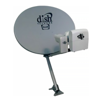
Assemble the antenna assembly without LNBF. Assemble the antenna assembly as
shown in Figure 1, except do not attach the LNBF assembly at this time.
1.
2.
3.
Elevation: Skew: Azimuth:
4.
5.