9
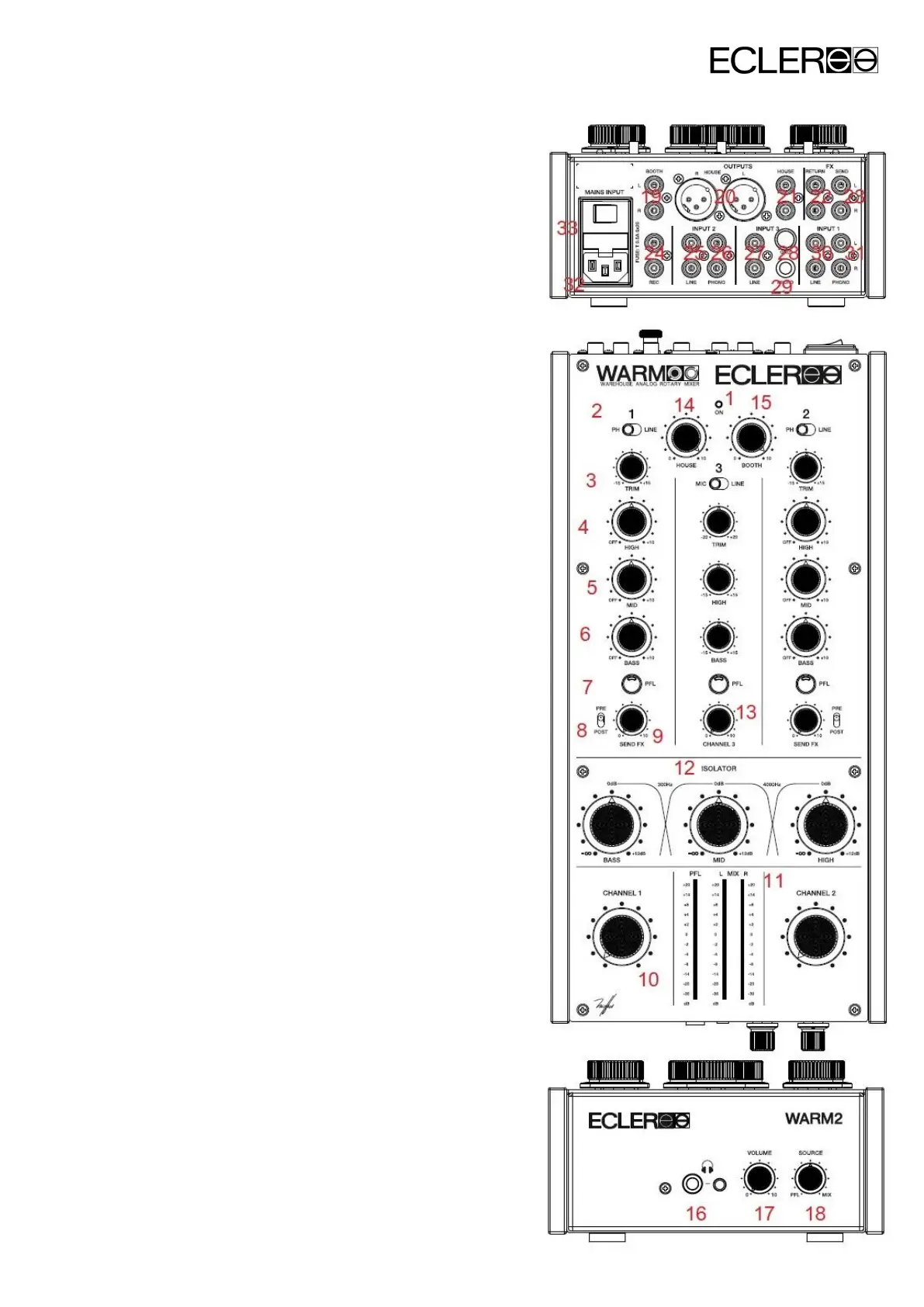
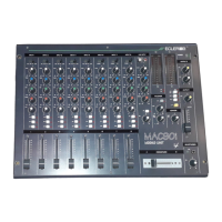
6. FUNCTION DIAGRAM
1. LED indicator ON
2. Input Selector (PHONO, LINE MIC)
3. Input sensitivity adjust, TRIM
4. Treble control, HIGH
5. Midrange control, MID
6. Bass control, BASS
7. Pre-Fader listening control, PFL
8. Send switch to effect bus, PRE/POST
9. Effect Send controller, FX SEND
10. Channel volume control
11. LED VU Meter
12. Isolator control
13. Channel 3 volume control
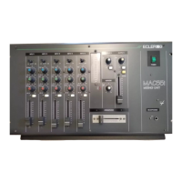
14. Master volume control, HOUSE
15. Monitoring volume control, BOOTH
16. Stereo J ack Headphones
17. Monitor Headphones Volume control
18. PFL/MIX monitoring control, SOURCE
19. RCA Monitoring Unbalanced Output, BOOTH
20. XLR Master Balanced Output, HOUSE
21. RCA Master Unbalanced Output, HOUSE
22. External FX return Input, FX RETURN
23. External FX send Output, FX SEND
24. Recording Output, REC
25. Line Input, LINE 2
26. Phono Input, PHONO 2
27. Line Input, LINE 3
28. Phono Ground Pin
29. Microphone Input, MICRO
30. Line Input, LINE 1
31. Phono Input, PHONO 1
32. Mains Socket
33. Power Switch