10
Eclipse TFB, V2, Installation Guide 310, 11/14/2014
Straight Run of Pipe Before a Metering Orifice
NOTE: There must be a straight run of pipe at least 10
pipe diameters before the burner metering orifice. Failure
to provide this distance will result in inaccurate pressure
drop readings, and possibly poor burner performance.
Pipe Connections
• Install a pipe union in the line to each burner. This
simplifies removal of the burner.
• The use of flexible pipe nipples in the air and gas
lines to the burner is optional.
• Flexible pipe nipples may cause higher pressure
drops than equivalent standard pipes, an additional
consideration when sizing air lines.
Avoid Large Pressure Drops
NOTE: The pressure drop of the gas and the air in the
piping is a critical parameter. Ensure that the size of all the
piping is large enough to prevent excessive pressure
loses and that the number of elbows is kept to a minimum.
If using a recuperator, pressure drops increase with the air
temperature. For the effects of the temperature on the
pressure drop, refer to the Combustion Engineering Guide
(EFE 825).
Install the Recuperator
Figure 3.8. Install the Recuperator
In radiant tube applications, TFB burners can be used in
conjunction with an exhaust leg recuperator.
■ Refer to the Moist PAK-D MSDS sheet for proper
PPE required when handling this product
• Insulate hot air piping and portion of recuperator
shown shaded in Figure 3.8 with “Moist PAK-D” by
Fiberfrax, Eclipse part #57325.
• DO NOT INSULATE THE BURNER.
• The use of flexible nipples in hot air piping is strongly
recommended to account for thermal expansion.
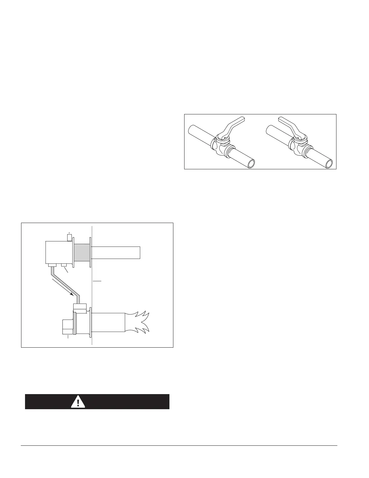
Step 2: Valve Installation
Valve Orientation
Install all the valves in such a way that the arrow (if
present) on the valve body points in the direction of flow.
Figure 3.9. Valve Orientation
Gas Cocks
Make sure that the handle of a gas cock is at a right angle
to the valve body when the valve is in the closed position.
This is an important position indicator. If you do not do this,
somebody may think that the gas cock is in the closed
position, while it is actually in the open position.
Gas Balancing Valves
A gas balancing valve is typically the same as a manual
butterfly valve. Refer to section below.
Manual Butterfly Valves
1. Install manual butterfly valves in accordance with
Bulletin/Info Guide 720.
2. Install manual butterfly valves in the gas line to the
burner (optional).
NOTE: It is recommended that there is a run of pipe with
a length of at least 10 pipe diameters between any flow
altering device and metering orifice on the burner.
Automatic Butterfly Valve
An automatic butterfly is driven by an actuator. Install the
control valve in accordance with Bulletin/Info Guide 720.
Ratio Regulator
• Connect an impulse line to the ratio regulator from
air supply line.
• Install the ratio regulator in accordance with Bulletin/
Info Guide 742.
Furnace
Wall
Exhaust
Ambient
Air
Gas Inlet
Hot
Air
TFB Burner
Recuperator
DANGER
Closed Open