9
Eclipse TFB, V2, Installation Guide 310, 11/14/2014
11. The disk end of the spark rod and flame rod should be
approximately 5/8" (16mm) past the face of the nozzle
(6).
12. The rods are adjustable at the threaded end of the
rod.
13. Tighten the compression nut on the rods after
positioning.
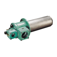
Figure 3.5. Assemble the Burner
14. Assemble the burner:
a. Install the rear cover (2) to the housing, (4) at the
relative position that you need to match the pipe
work.
b. Install the four washers and bolts (1).
15. Reconnect the piping.
Step 2: Install the UV Scanner (if required)
Figure 3.6. Position of the UV Scanner
■ If combustion air is preheated, the UV scanner
must be protected from high temperatures. Install
the UV scanner with a heat block seal and supply
cooling air. See Bulletin 834.
1. Install the UV Scanner and, if necessary, the heat
block seal in the opening (2).
2. Make sure the UV scanner is connected to the
electrical circuit of that burner.
Flame monitoring controls that stop the spark as soon as
a signal is detected may prevent establishment of flame,
particularly when using UV scanners. The flame
monitoring control must maintain the spark for a fixed time
interval that is long enough for ignition
■ Connecting the flame sensor of a burner to the
electrical circuit of the wrong burner can cause
fires and explosions.
The UV scanner must be compatible to the flame
monitoring control that is used. Refer to the manual of
your selected control for proper selection of the scanner.
■ Adjustments may vary from Eclipse published
values if the flame controls other than those
recommended in the Design Guide are used.
Consult with the engineer who specified the
alternate control for limitations.
Burner Installation
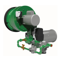
Figure 3.7. Install the Burner
Step 1: Install the Burner
Dimensions
For full information on the burner dimensions, refer to the
appropriate Datasheet: 310-1 (TFB030); 310-2 (TFB075);
310-3 (TFB200).
The burner will bolt to the tube flange. Align the air and
gas to accommodate accepted piping practices.
Flame Sensor;
UV Scanner
CAUTION
DANGER
NOTICE
Pipe
Union
10
Pipe
Ø
Integral Air
Orifice
Integral Gas
Orifice