E C O P H Y S I C S Measurement principle
CLD 780 TR / July 2000 22
3.2.5 CLD 780 TR Electronics
The following is a description of the electronic modules in the instrument,
and their functions. Refer to the CLD 780 TR block diagram (Fig 3.3). The
numbers in parentheses refer the components so labeled in the block dia-
gram.
Power supply board: (PONOX [1])
The power supply of the CLD 780 TR is characterized by its high effi-
ciency. This is achieved by utilizing switching converters for the main
loads, Peltier cooler and for the +5V supply to the logic board and the
display.
A high quality line filter [2] keeps electrical disturbances from entering the
instrument from the external power supply and vice versa. The solenoid
valve is powered by a solid-state relay on the PONOX TR780 board.
Control board: (LONOX [3])
All measuring and control tasks, as well as the data import and export
through the keypad, display, RS232 and analog outputs are handled by
the LONOX. Calibration and operating data are stored in battery backed
memory, which also powers a real time clock.
Photomultiplier cooler control:
A cooler unit [4] reduces dark current and noise in the PMT. The actual
temperature is not monitored. The cooler module may be manually
switched off in “TEST“ mode, but is otherwise always active.
Temperature regulation: (LONOX, PONOX)
The thermal stabilization of the sample inlet to the main chamber is per-
formed using an insulated heating foil [6] and semiconductor temperature
sensor [5].
Pressure measurement: (PREST [7])
The chamber pressure is measured by a temperature-compensated abso-
lute pressure sensor. The output signal is amplified on the PREST board
and transmitted to the LONOX board where it is continually monitored.
Detector unit: (PPTFE [9], PMT [8])
In the cooled head-on-PMT [8] each photon triggers a short current pulse.
The pulse is amplified and very quickly processed and validated by a fast
comparator unit (PPTFE) [9]. Valid current pulses are passed on to the mi-
croprocessor, where they are counted and converted into measurement
values.
Command and data I/O: Keypad, Display, Inputs & Outputs (IFNOX,
[10])
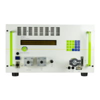
Direct communication with the instrument is achieved through a keypad
with 4 x 5 keys [11] and a vacuum fluorescent alphanumeric display with
2 x 40 characters [12]. Additionally, an RS-232 asynchronous interface
 Loading...