E C O P H Y S I C S Calibration
CLD 780 TR / July 2000 89
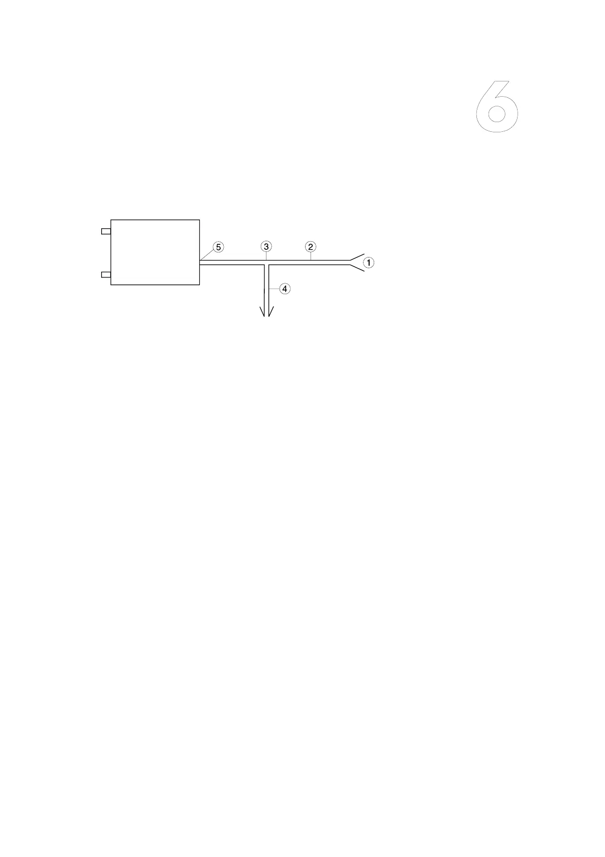
Fig. 6.1
”Connection drawing for calibra-
tion of a CLD 780 TR“
The information given in brackets
applies if the CLD has been orde-
red without the PLC 762.
1. Connection to the calibration
device
2. Connecting tubing between
calibration device and PLC
762 (CLD 780 TR)
– calibration gas flow: 4.5
l/min (total flow incl. excess
flow)
3. T-connector
4. Bleed line to the ambient air
– excess flow: > 1.5 l/min
5. Cal. gas inlet on the PLC
762 ( or sample inlet to CLD
780 TR)