Figure 4
Figure 5
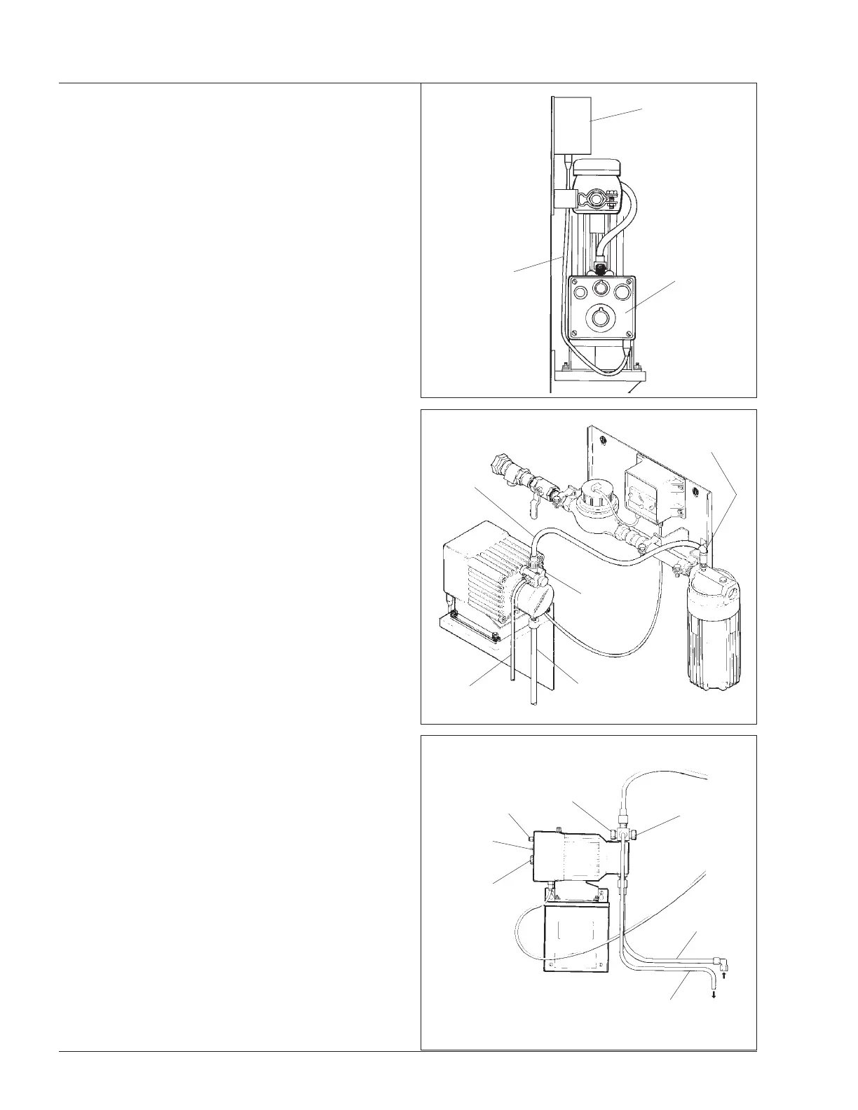
Figure 6
NOTE - insure pump is mounted close enough to flow
meter manifold assembly for the length of cable con-
nector wire available from the programmable divider.
5. Using the drum probe, 1/2" (12.7mm) tubing and fittings
provided, plumb the drum probe to the bottom connector
on the pump head,
refer to Figure 5.
NOTE - For products that gas off, do not use the drum
probe. The tubing should be flexible and as short as
possible. The product drum must be placed directly
under the pump.
Using the 1/2" (12.7 mm) tube and hose clamp provided,
plumb the output port, which is the one on the top of the
anti-siphon valve on the pump, to the injection point on the
mixing chamber of the manifold assembly. Connect the
pump to 120VAC/60Hz electrical supply.
Connect 1/4" (6.4 mm) tubing, which is provided to the
tubing nut on the anti-siphon valve on the pump head, and
run it back to the drum or the drain. This is for pressure
relief during priming.
6. Place the pump switch in the INTERNAL position. As the
pump is running, set the stroke length knob at 60% (all
dosage ratio calculations are based on 60% stroke length),
refer to Figure 6.
Set the speed control switch on the pump at 100% and
with the pump switch in the internal position, grasp the
black and yellow knob on the pump anti-siphon valve and
pull outward on both until the product rises in the suction
tube and starts to come out the 1/4" (6.4 mm) bypass tube.
(Priming is best accomplished with the speed switch set
on 100%). The pump is now primed.
SET THE SELECTOR SWITCH ON THE PUMP TO THE
EXTERNAL POSITION.
4
PUMP CONTROL
PANEL
OUTPUT
TUBING
DRAIN
TUBING
DRUM PROBE
TUBING
ANTI-SIPHON
VALVE
INJECTION
POINT
YELLOW
KNOB
BLACK
KNOB
SPEED
CONTROL
PUMP
SWITCH
STROKE
LENGTH
FROM
PRODUCT
TO DRAIN
PROGRAMMABLE
DIVIDER
PUMP TO
PROGRAMMABLE
DIVIDER
CONNECTION
 Loading...


