4
GeneralSpecificaons&DescriponofMachine
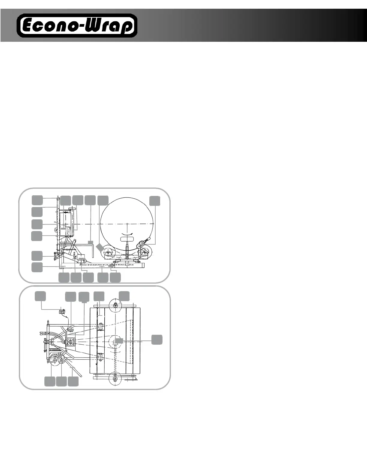
Themainframe(1)ofthewrapperisaachedtothethree‐
pointsuspensionsystemofthetractor.Thelowerframe(2)is
fixedtothemainframeusingtwobolts(8)securedwithresili‐
entretainingpins.Arota
ngframe(3)withrollers(9),upon
whichbalesareloaded,ismountedonthelowerframe.Abar‐
rier(12)andafilmdispenserareinstalledonthevercalbeam
(11)ontherightsideofthemainframe.Bothvercalbeams
(11)areconnectedatthe
topwithaU‐profile(13).Thewrap‐
perispoweredfromthehydraulicinstallaonofthetractor
withahydraulicmotor(5)throughaspecialvalve(14),which
ensuresasmoothstart‐upandstoppingoftherotangframe.
Thepowerfromthehydraulicmotoris
transmiedontothe
chainwheeloftherotangframewitha5/8”chain(15).Inthis
way,aerthedriveisturnedon,therotangframeofthe
wrapper(togetherwiththebalebeingwrapped)r otates
aroundthevercalaxis.Intherotangframe(3),
thereisan
openbevelgearbox(10).
Fig.7Diagramoftheself-loadingbalewrapper
1‐mainframe;2‐lowerframe;3‐rotangframe;4‐filmdispenser;5‐
hydraulicsystem;6‐resistancewheels;7‐wrappingcounter;8‐pin;9‐
roller;10‐bevelgearbox;11‐vercalbeam;12‐barrier;13‐con‐
necngU‐profile;
14‐specialvalve;15‐mainchain;16‐rubberrollers;
17‐rolloffilm;18‐retainingpin;19‐line;20‐securingchain;21‐film
cuer;22‐countersensor
Thesubsequentla yersoffilmarewrappedaroundthe
baleasaresultoftheaforemenonedmoons.The
filmdispenser(4)consistsofaframeandasupport
bracketwithrubberrollers(16)coupledwitheach
otherbymeansofaspurgear.A
rollofwrappingfilm
(17)isinstalledontheboltinthe
dispenserframeinaccordancewiththediagram
(seeFig.11).Theappropriatelyselectedposionbe‐
tweentherubberrollersandcloseadhesionofthefilm
(17)totherollers(16)ensuresstretchingandgoodand
accurateadhesiontothesubsequentfilmlayers.
The
degreeoffilmlengtheningcanbeadjustedbyturning
thefilmrollpressurenut(see
Fig.11,item3).Thelowerfr ame(2)withtherotang
frame(3)issecuredagainstlngbythelockingpin
(18),whichissituatedonthemainframe(1).When
the
lockingpin(18)ismovedforwardbytheleversystem
aerpullingtheline(19)fromthetractorcabresultsin
unlockingthelowerframe(2),togetherwiththero‐
tangframe(3).Aerliingthewrap
Acuer(21)withrollerknivesfor
filmcungisfixedto
therotangframe(3)bytherollerdrives(9).Thefilm,
whichwaspulledoutoftheinsertedbale,willbeintro‐
ducedbetweenthecuerflatbars(21)ontotheroller
knivesandcutoff.Rubberresistancewheels
(6)
areplacedontransversebarsoftherotang
frame(3),whichprotectthebaleagainstslidingof
theroller,whileitisbeingwrapped.Whiletrans‐
porngthewrapperonpublicroads,the
transportcovermustbeplaced,insteadofoneofthe
retainingwheelsand thetriangularsign
andthewarn‐
ingsignshouldbeplacedonthebracketsthatare
placedonit.Thebalewrapperisequippedwith
anelectronicwrappingcounter(7).Thecountersensor
(22)isinstalledonthesupportbracketopeningonthe
rightsideofthemainframe(1),whilethewrapping
counter
shouldbeplacedinavisibleplaceinthetractor
cabandthecableshouldbeconnectedtothesensor
(22).
1
214
15 8
5
11
17
12
13
19
18
4
9
21
16
16
12
17
3
22
10
8
7
6
22
20