16
Installing the Motherboard
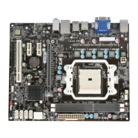
F_AUDIO: Front Panel Audio header
This header allows the user to install auxiliary front-oriented microphone and line-
out ports for easier access.
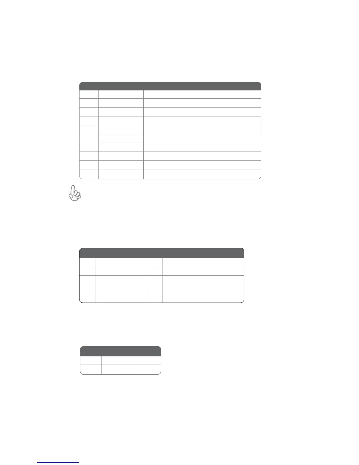
F_USB1~2: Front Panel USB 2.0 headers
The motherboard has four USB 2.0 ports installed on the rear edge I/O port array.
Additionally, some computer cases have USB 2.0 ports at the front of the case. If you
have this kind of case, use auxiliary USB 2.0 connector to connect the front-
mounted ports to the motherboard.
Please make sure that the USB cable has the same pin assignment as
indicated above. A different pin assignment may cause damage or system
hang-up.
1 USBPWR Front Panel USB Power
2 USBPWR Front Panel USB Power
3 USB_FP_P0- USB Port 0 Negative Signal
4 USB_FP_P1- USB Port 1 Negative Signal
5 USB_FP_P0+ USB Port 0 Positive Signal
6 USB_FP_P1+ USB Port 1 Positive Signal
7 GND Ground
8 GND Ground
9 Key No pin
10 USB_FP_OC0 Overcurrent signal
Function
Pin Signal Name
Pin Signal Name Function
1 PORT 1L 2 AUD_GND
3 PORT 1R 4 PRESENCE#
5 PORT 2R 6 SENSE1_RETURN
7 SENSE_SEND 8 KEY
Pin Signal Name
9 PORT 2L 10 SENSE2_RETURN
Pin Signal Name
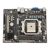
CASE: Chassis Intrusion Detect Header
Short Chassis cover is removed
Open Chassis cover is closed
Pin 1-2 Function
This detects if the chassis cover has been removed. This function needs a chassis
equipped with instrusion detection switch and needs to be enabled in BIOS.