17
Installing the Motherboard
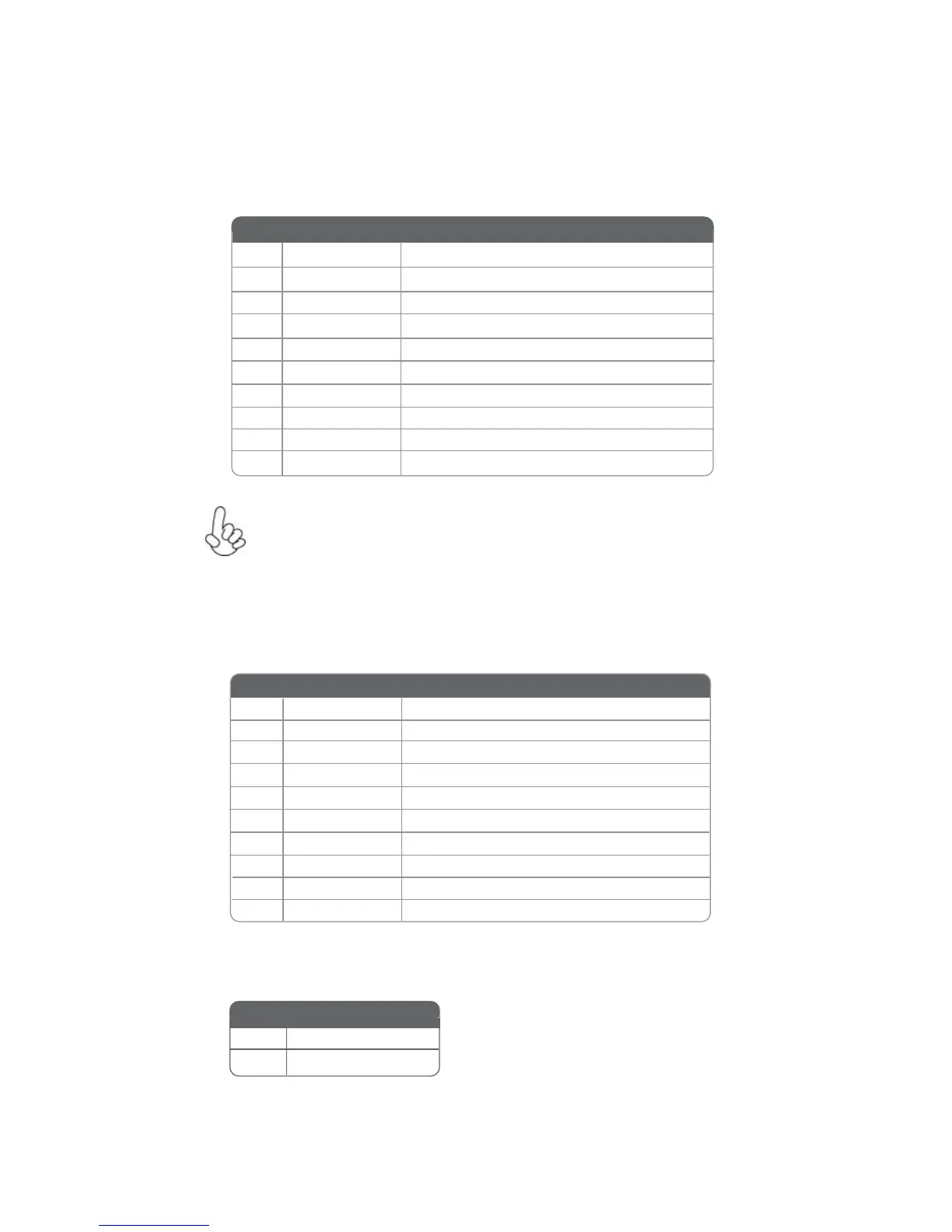
F_USB1~2: Front Panel USB headers
The motherboard has two USB 2.0 headers supporting four USB 2.0 ports. Addition-
ally, some computer cases have USB ports at the front of the case. If you have this
kind of case, use auxiliary USB connector to connect the front-mounted ports to the
motherboard.
Please make sure that the USB cable has the same pin assignment as
indicated above. A different pin assignment may cause damage or system
hang-up.
1 USBPWR Front Panel USB Power
2 USBPWR Front Panel USB Power
3 USB_FP_P0- USB Port 0 Negative Signal
4 USB_FP_P1- USB Port 1 Negative Signal
5 USB_FP_P0+ USB Port 0 Positive Signal
6 USB_FP_P1+ USB Port 1 Positive Signal
7 GND Ground
8 GND Ground
9 Key No pin
10 NC Not connected
Pin Signal Name Function
COM: Onboard serial port header
Connect a serial port extension bracket to this header to add a serial port to your
system.
1 DCDB Data Carrier Detect
2 SINB Serial Input
3 SOUTB UART B Serial Output
4 DTRB UART B Data Terminal Ready
5 GND Ground
6 DSRB Data Set Ready
7 RTSB RART B Request to Send
8 CTSB Clear to Send
9 RI Ring Indicator
10 Key No pin
Pin Signal Name Function
ME_UNLOCK: ME Unlock Header
Short Unlock
Open Lock
Pin 1-2 Function
 Loading...