21
Installing the Motherboard
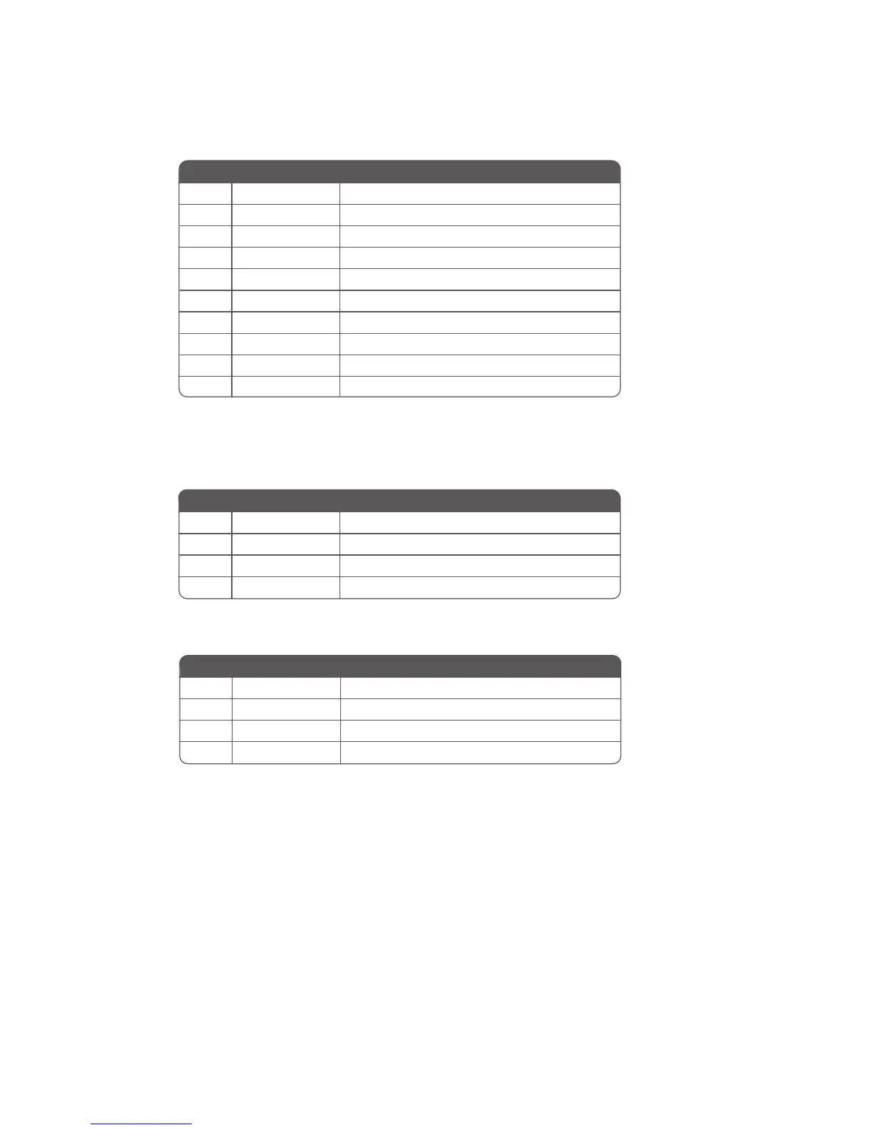
AUDIO1: Front Panel Audio header
This header allows the user to install auxiliary front-oriented microphone and line-out ports
for easier access.
AUXIN1: Auxiliary In header
This connector is an additional line-in audio connector. It allows you to attach a line-in
cable when your rear line-in jack is set as line out port for 4-channel function.
1 AUD_MIC Front Panel Microphone input signal
2 AUD_GND Ground used by Analog Audio Circuits
3 AUD_MIC_BIAS Microphone Power
4 AUD_VCC Filtered +5V used by Analog Audio Circuits
5 AUD_F_R Right Channel audio signal to Front Panel
6 AUD_RET_R Right Channel Audio signal to Return from Front Panel
7 REVD Reserved
8 Key No Pin
9 AUD_F_L Left Channel Audio signal to Front Panel
10 AUD_RET_L Left Channel Audio signal to Return from Front Panel
1 AUX_L AXU In left channel
2 GND Ground
3 GND Ground
4 AUX_R AXU In right channel
CDIN1: Analog Audio Input connector
Pin Signal Name Function
Pin Signal Name Function
1 CD in_L CD In left channel
2 GND Ground
3 GND Ground
4 CD in_R CD In right channel
Pin Signal Name Function