Page 6 of 40
INSTALLATION
Installation Requirements
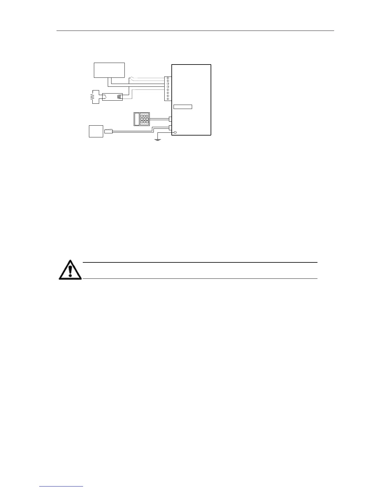
The typical wiring schematic is shown in Figure 1.
Figure 1: Typical EDAC 400-02 Installation
Power Supply
A DC regulated power supply complying with Telecom PTC101 or ACA regulations is required
(such as EDAC PB12). The DC power supply should be normally constant, between 12 and 15
volts. An optional battery backup power supply (EDAC PB12) is required to maintain operation
during a mains failure event.
Input Triggers
The input trigger causes the EDAC 400-02 to commence the dialling sequence. A clean contact,
voltage-free input is required. This would normally be via an external relay or switch. The EDAC
400-02 is configured by default for a normally open type input. Alternatively the user can
configure any of the inputs to accept a normally closed type input (see function F52).
Some examples of these types of triggers might be a relay output, a micro-switch or a float
switch. Any of the inputs can be configured as either an input or an output (see function F08).
NOTE: The activating trigger must be installed correctly and maintained to
prevent false triggering.
Earth Discharge
The EDAC 400-02 has a separate Earth Discharge Circuit, which is used to protect the EDAC
400-02 and any attached equipment from lightning strikes and other external high voltage
transients, which may travel down the phone line. The Earth Discharge circuit must be connected
to a common earth point. These are usually found at a switch board earth point (earth buss bar).
The Earth Discharge should be connected using a M3 ring terminal to the bottom right PCB
screw (near phone/line sockets).
 Loading...