– 1 –
Quick Start Guide
1. Unpack the Switch and Check Contents
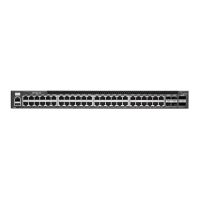
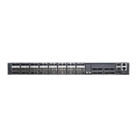
AS6700-32X / AS6701-32X
40G Data Center Switch
Rack Mounting Kit—contains two brackets and eight
screws for attaching the brackets to the switch
Grounding Wire
Power Cord—either Japan, US, Continental Europe
or UK
Console Cable—RJ-45 to DB-9
Documentation—Quick Start Guide (this document)
and Safety and Regulatory Information
Note:
For information on switch software, refer to
www.edge-core.com.
Switches with part numbers 6700/6701-32X-D*-********
have switch software pre-loaded on the switch. Software
user documentation can be found at www.edge-core.com.
Switches with part numbers 6700/6701-32X-O-********
have the Open Network Installer Environment (ONIE)
software installer pre-loaded on the switch, but no switch
software image. Information about compatible switch
software can be found at www.edge-core.com.
Caution:
The switch includes plug-in power supply and
fan tray modules that are installed into its chassis. All
installed modules must have a matching airflow direction.
That is, all modules must have a front-to-back (F2B) airflow
direction, or all modules must have a back-to-front (B2F)
airflow direction. The airflow direction of PSU and fan tray
modules is indicated by labels on the modules.
2. Mount the Switch
Attach the brackets to the switch.
Use the screws supplied with the rack to secure the switch in
the rack.
Caution:
Installing the switch in a rack requires two
people. One person should position the switch in the rack,
while the other secures it using the rack screws.
3. Ground the Switch
Ensure the rack on which the switch is to be mounted is
properly grounded and in compliance with ETSI ETS 300 253.
Verify that there is a good electrical connection to the
grounding point on the rack (no paint or isolating surface
treatment).
Attach the grounding wire to the grounding terminal on the
switch rear panel, then to rack ground.
Caution:
The earth connection must not be removed
unless all supply connections have been disconnected.
4. Connect Power
Install one or two universal AC power modules in the switch.
The switch supports up to two PSUs that must have the
same matching airflow direction as the installed fan trays.
Connect an external AC power source to the modules.
5. Verify Switch Operation
Verify basic switch operation by checking the system LEDs.
When operating normally, the Sys LED should be on green.
E012014-CS-R01
150200000827A
www.edge-core.com
32-Port 40G Data Center Switch
AS6700-32X / AS6701-32X