– 1 –
Quick Start Guide
1. Unpack the Switch and Check Contents
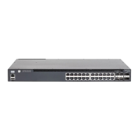
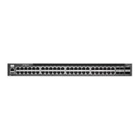
AS4610-54T (B)
Rack Mounting Kit—two brackets and eight screws
Four adhesive foot pads
Two Power Cords—either Japan, US, Continental
Europe or UK
Console Cable—RJ-45 to DB-9
Micro-USB to Type A USB Cable
Documentation—Quick Start Guide (this document)
and Safety and Regulatory Information
Note:
For information on switch software, refer to
www.edge-core.com.
Switches with part numbers 4610-54-O-******** have the
Open Network Installer Environment software installer pre-
loaded on the switch, but no switch software image.
Information about compatible switch software can be
found at www.edge-core.com.
Warning:
For indoor use only. The switch, AC power, and
all connected cables are not designed for outdoor use.
2. Mount the Switch
Attach the brackets to the switch.
Use the screws and cage nuts supplied with the rack to
secure the switch in the rack.
Caution:
Installing the switch in a rack requires two
people. One person should position the switch in the rack,
while the other secures it using the rack screws.
Note:
The switch can also be installed on a desktop or shelf
using the included adhesive rubber foot pads.
3. Ground the Switch
Ensure the rack on which the switch is to be mounted is
properly grounded and in compliance with ETSI ETS 300 253.
Verify that there is a good electrical connection to the
grounding point on the rack (no paint or isolating surface
treatment).
Attach a lug (not provided with PSU) to a #18 AWG minimum
grounding wire (not provided with PSU), and connect it to
the grounding point on the switch rear panel. Then connect
the other end of the wire to rack ground.
Caution:
The earth connection must not be removed
unless all supply connections have been disconnected.
4. Connect Power
Install one or two universal AC PSUs in the switch.
Connect an external AC power source to the PSUs.
5. Verify Switch Operation
Verify basic switch operation by checking the system LEDs.
When operating normally, the PSU1/PSU2 and System LEDs
should all be on green.
E102016-AP-R01
150200001512A
www.edge-core.com
48-Port GE Top-of-Rack Switch
AS4610-54T (B)