– 2 –
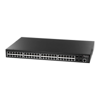
4. Connect AC Power
Plug the AC power cord into the socket on the rear of the
switch.
Connect the other end of the power cord to an AC power
source.
Note:
For International use, you may need to change the AC
line cord. You must use a line cord set that has been
approved for the socket type in your country.
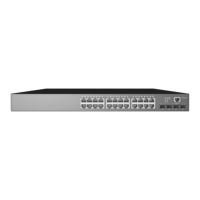
5. Verify Switch Operation
Verify basic switch operation by checking the system LEDs.
When operating normally, the Power and Diag LEDs should
be on green.
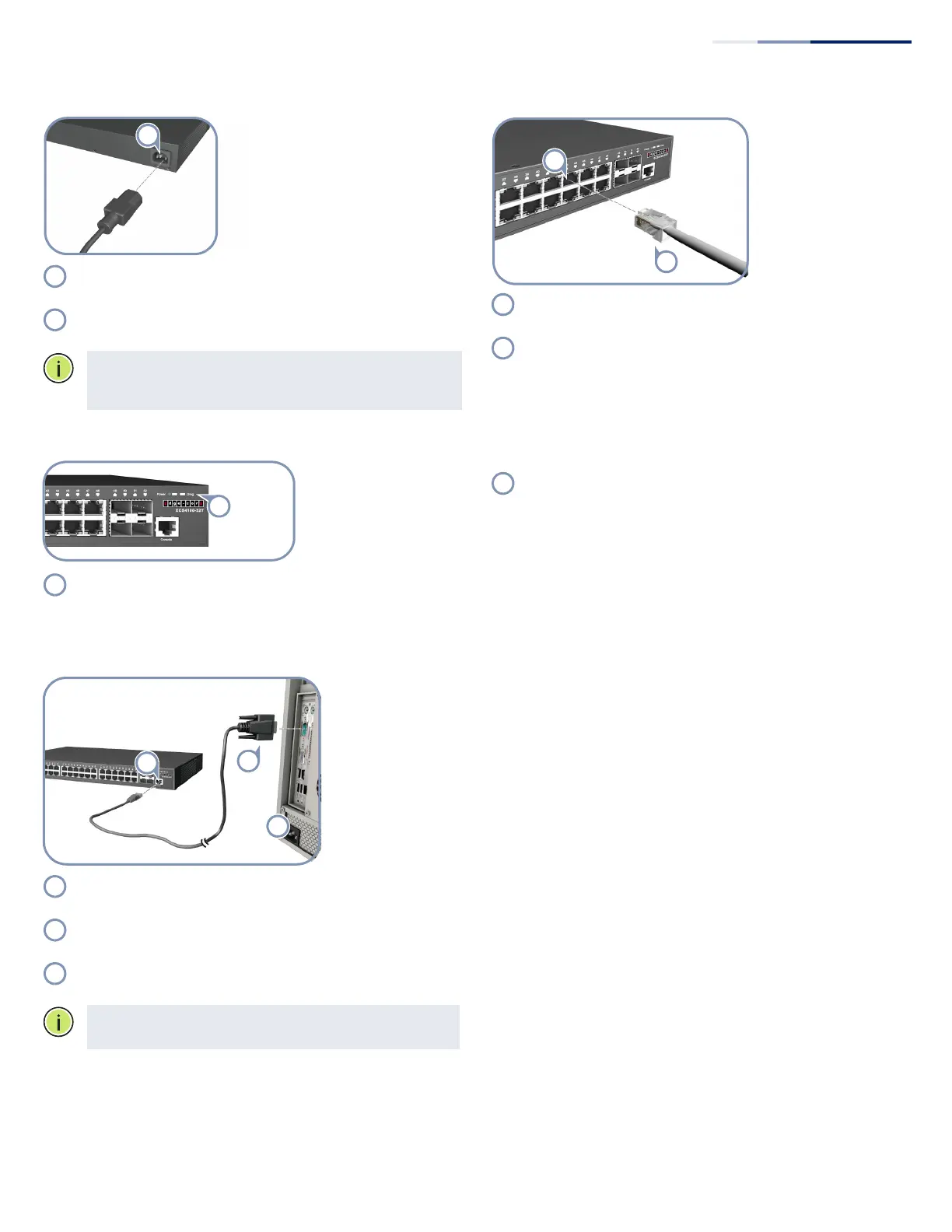
6. Perform Initial Configuration
Connect a PC to the switch console port using the included
console cable.
Configure the PC’s serial port: 115200 bps, 8 characters, no
parity, one stop bit, 8 data bits, and no flow control.
Log in to the CLI using default settings: Username “admin”
and password “admin.”
Note:
For further information on switch configuration, refer
to the Web Management Guide and CLI Reference Guide.
7. Connect Network Cables
For RJ-45 ports, connect 100-ohm Category 5, 5e or better
twisted-pair cable.
For the SFP/SFP+ slots, first install SFP/SFP+ transceivers and
then connect fiber optic cabling to the transceiver ports. The
following transceivers are supported:
1000BASE-SX (ET4202-SX)
1000BASE-LX (ET4202-LX)
1000BASE-RJ45 (ET4202-RJ45)
1000BASE-EX (ET4202-EX)
1000BASE-ZX (ET4202-ZX)
As connections are made, check the port status LEDs to be
sure the links are valid.
On/Blinking Green — Port has a valid link. Blinking
indicates network activity.
On Amber — Port is supplying PoE power.
Quick Start Guide