EasyManua.ls Logo

Edge-Core ECS4120-52T

Edge-Core ECS4120-52T
9 pages
To Next Page IconTo Next Page
Loading...
– 1 –
Quick Start Guide
1. Unpack the Switch and Check Contents
ECS4120-28T
ECS4120-28Fv2
ECS4120-28Fv2-I
ECS4120-52T
28T/52T Mounting Kit — 4 brackets and 10 screws
28Fv2/28Fv2-I Mounting Kit — 2 brackets and 4 screws
Four adhesive foot pads
Power cord — US, Continental Europe, or UK
Console cable — RJ-45 to DB-9
Documentation—Quick Start Guide (this document)
and Safety and Regulatory Information
2. Mount the Switch
a. Mounting in a Rack
Attach the brackets to the front of the switch.
Use the screws and cage nuts supplied with the rack to
secure the switch in the rack.
Caution:
Installing the switch in a rack requires two
people. One person should position the switch in the rack,
while the other secures it using the rack screws.
Attention:
L’installation de l’appareil dans un rack
nécessite deux personnes. Une personne doit positionner
l’appareil dans le rack, tandis que l’autre le fixe à l’aide des
vis du rack.
2
1
1
2
Note:
The switch can also be installed on a desktop or shelf
using the included adhesive rubber foot pads.
b. Mounting on a Wall
Caution:
Wall mount the switch with the network ports
facing down.
Attention:
Montez le commutateur au mur, les ports
réseau orientés vers le bas.
Caution:
Wall mount the switch using four brackets
(included) attached to the front and rear of the switch.
Attention:
Montez l'interrupteur au mur à l'aide de quatre
supports (inclus) fixés à l'avant et à l'arrière de l'interrupteur.
Rotate the brackets 90 degrees and attach them to the front
and rear of the switch. Use three screws for the front brackets
and two screws for the rear brackets.
In the required location, mark and drill eight holes in the wall
for the wall anchors (not included).
Note:
For a wood wall, drilling holes and using wall anchors
is not required.
Mount the switch on the wall and secure it in place using
eight #12 wood screws (5/8-inch, not included).
3. Ground the Switch
Ensure the rack on which the switch is to be mounted is
properly grounded and in compliance with ETSI ETS 300 253.
Verify that there is a good electrical connection to the
grounding point on the rack (no paint or isolating surface
treatment).
3
3
1
1
2
2
1
2
3
1
2
1
28-Port and 52-Port L2 Gigabit Ethernet Switches
ECS4120 Series
www.edge-core.com
E022023-AP-R06
150200001742H
*150200001742h_R06*

Other manuals for Edge-Core ECS4120-52T

Question and Answer IconNeed help?

Do you have a question about the Edge-Core ECS4120-52T and is the answer not in the manual?

Edge-Core ECS4120-52T Specifications

General IconGeneral
Device TypeManaged Switch
Switching Capacity176 Gbps
Forwarding Rate131 Mpps
MAC Address Table Size16K
DRAM512 MB
Ports48 x 10/100/1000BASE-T
Jumbo Frame SupportUp to 9KB
CPU800MHz
Power SupplyAC 100-240V, 50-60Hz
Operating Temperature0°C to 50°C
Storage Temperature70 °C
Dimensions (W x D x H)440 x 44 mm
LayerLayer 2 / Layer 3 Lite
Humidity10% to 90% (non-condensing)

Summary

Unpack the Switch and Check Contents

Included Components

Lists all items included in the switch package, such as mounting kits, cables, and documentation.

Mount the Switch

Mounting in a Rack

Instructions for physically installing the switch into a standard equipment rack using brackets and screws.

Mounting on a Wall

Guidance for securing the switch to a wall, including bracket placement and screw requirements.

Ground the Switch

Grounding Procedure

Details on how to properly connect the switch to ground for safety and electrical protection.

Connect Power

AC Power Connection

Steps for connecting the switch to an AC power source using the provided power cord.

DC Power Connection

Instructions for connecting the switch to a DC power source, including warnings and wire specifications.

Verify Switch Operation

LED Status Check

How to check basic switch functionality by observing the system LEDs for normal operation.

Perform Initial Configuration

Console Port Configuration

Steps to connect a PC to the console port and configure serial settings for initial access.

Connect Network Cables

RJ-45 Port Cabling

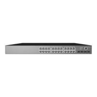
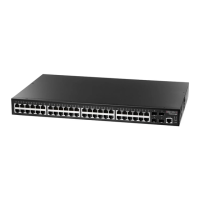
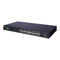
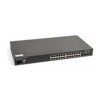
Guidance on connecting network cables to RJ-45 ports using appropriate twisted-pair cables.

SFPSFP+ Slot Cabling

Instructions for installing transceivers and connecting fiber optic cables to SFP/SFP+ slots.

Port Status Indicators

Explanation of port status LEDs and their meaning regarding network activity and link status.

Hardware Specifications

Physical Dimensions and Weight

Details on the switch's size, weight, and chassis specifications for different models.

Environmental Requirements

Specifies operating and storage temperature, and humidity levels for the switch.

Power and Consumption

Information on AC/DC input power requirements and maximum power consumption for various models.

Regulatory Compliance

Lists emissions, immunity, safety, and regional compliance standards the switch adheres to.

Related product manuals