14
ENGLISH
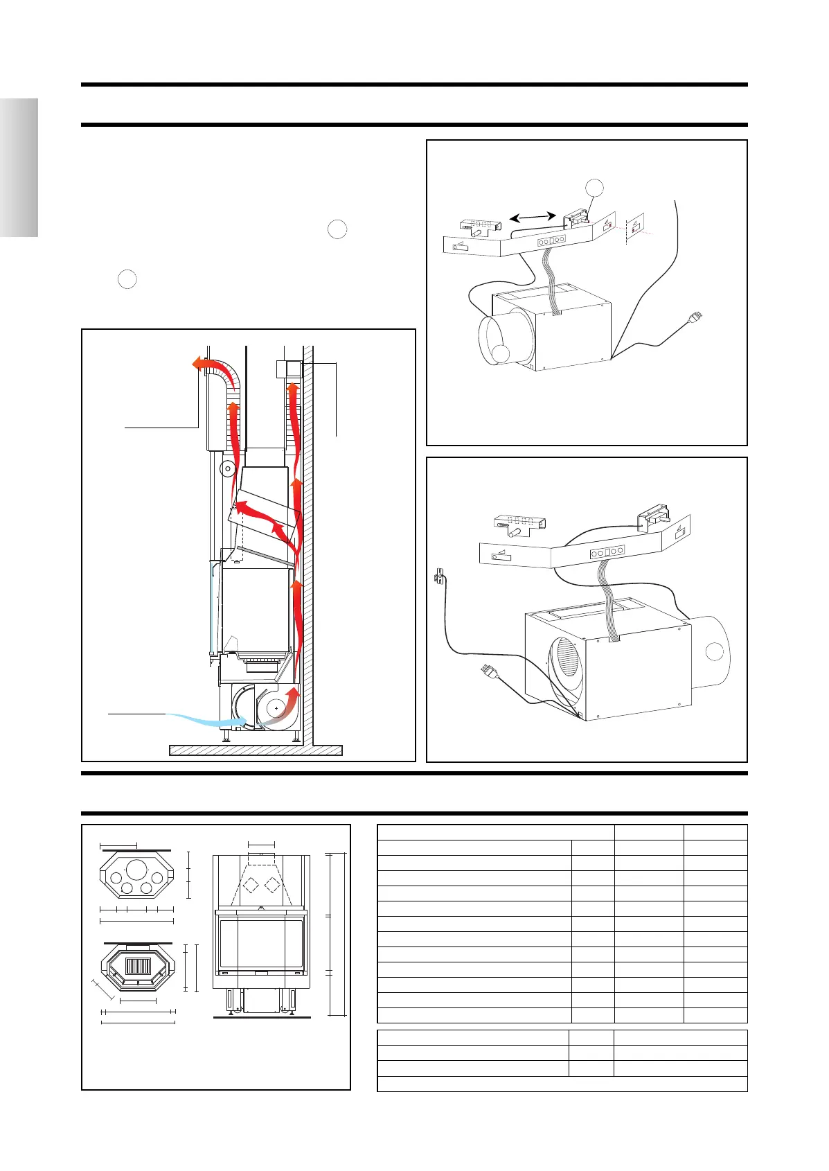
THE TECHNOLOGY
HOT AIR CIRCULATION DIAGRAM (4 OUTLETS)
outside + indoor
air inlet
hot air outlet
N V
power output kW
1
6
1
6
wood consumption kg/h
4,8 4,8
efficiency %
7
1,9
7
1,9
smoke outlet Ø cm 25 25
Ø stainless steel flue for 5m sup. cm 22 22
Ø stainless steel flue for 3-5m h cm 25 25
weight including packaging kg 271 278
air intake section cm 300 300
Ø hot air outlet channelling cm 14 14
fan noise level db (A) - 56-58
maximum fan capacity m
3
/h - 800
heating capacity m
3
415 415
fan motor power W 90
power supply Vac 230
frequency Hz 50
fuse amperage = see technical specifications sheet attached to the control unit
• AIR INTAKE MECHANISM
the air is drawn in from the outside and mixed with the air
inside using a new wire controlled mechanism recessed in
the bottom front panel of the firebox.
When the fireplace is operating control lever 1b must be par-
tially or fully positioned to the right (room + outside air).
fitting 4b , the sensor cables and the 230 Vac power supply
can be positioned independently either to the left or to the
right.
hot air outlet
SPECIFICATIONS
4b
4b
1b
A
C
*
*
*
*
*
47,5
95
21
21
2514
14
23
14
23
160
59
2
2
5
53
39
Ø 25
4
46
10
60
95
5,5
84
46
5,5
27
7,5
hot air outlet pipes
230 Vac
power supply
sensor
heating air damper control
230 Vac power
supply
Closed
Open
sensor to be placed
on hot air outlet
channel
(see p. 19 fig. O)
sk multi STATUS plus cod 672140:Layout 1 23/01/2012 18.00 Pagina 15