Wiring DiagramsAdvanced Setting
06. Rle Setting of passive linkage and main output, press “ ” or
“ ” to change the condition of linkage; “00” means
correspond with main loop output, “01” means opposite.
Press “ ” to enter into next setting.
07. Dly Dry contact function output delay: Press “ ” or “ ” to
amend from 0-5minutes, press “ ” to enter into next
setting.
When the output from “ON” to “OFF”, dry contact will be “OFF”
at the same time.
08. Hit Press “ ” or “ ” to adjust the max.temp. from 35~60℃.
Press “ ” to enter into next setting.
09. Fac Recover factory setting, press “ ”, then the coin
“-” appears on the screen, hold on until it changes to “- -”,
finishes recover factory setting. Press “ ” to enter into
next setting; or press “ ” to save and exit of setting .
Setting
01 02 03 04 05 0 6 07 08
Default
0 IN 35 1 5 00 00 3 5
The highest elevation for the controller working under full load
situation is 2500m; or if higher than 2500m, the rated power of
external loads should be≤80% rated power of the thermostat.
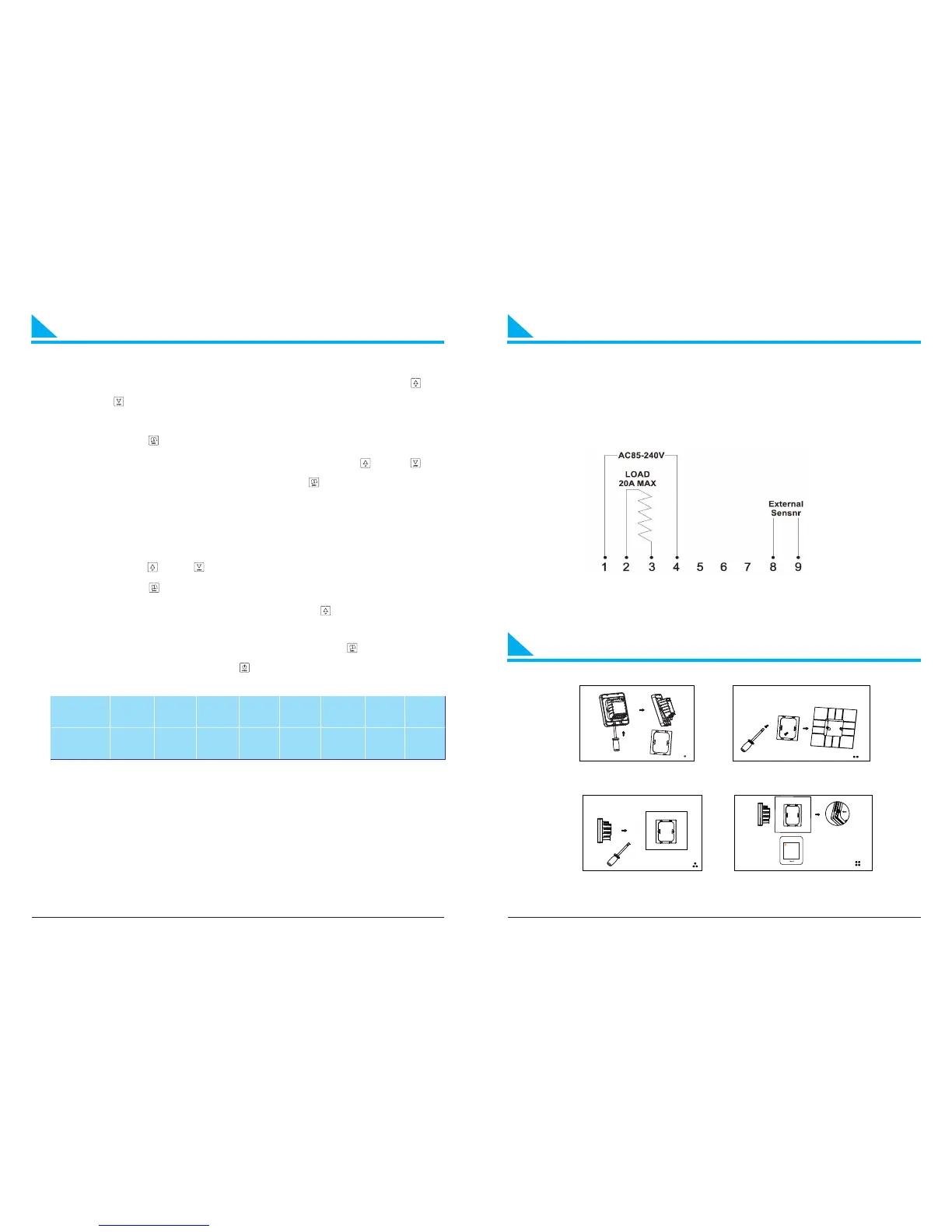
Installation Diagrams
9
10
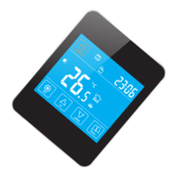
Wiring diagrams
1. Insert the screwdriver into the gap to detach
the back cover and iron plate of the thermostat
2. Fix the iron plate with screw and install it on
the junction box in the wall
3.To correctly connect the wires as the wiring diagram
4.Insert the thermostat and fix it on the iron plate