C410-01-882 Issue B
Page 3 © Edwards Limited 2009. All rights reserved.
Edwards and the Edwards logo are trademarks of Edwards Limited.
This page has been intentionally left blank.
3 Installation notes
1. Connection to the water supply should be made using 12 mm bore tubing and to the vacuum system using 7 mm
bore vacuum tubing. If it is desired to fit a water drain, thus should be of 9.5 mm bore tubing.
Note: After considerable service, the tubing may stick to the nozzles and it should be removed by cutting.
2. Should the jet nozzle assembly or the vacuum connection be removed:
Ensure ball valve is located correctly in the vacuum arm, on re-assembly, so that the pin projects towards
the centre line of the jet nozzle assembly.
The vacuum nozzle should be carefully tightened to a torque setting not exceeding 18 lbf in (maximum) and
the jet nozzle to a torque setting not exceeding 24 lbf in (maximum).
The ball valve is manufactured from an elastomer which is liable to swell in the presence of certain chemical
(particularly ketones and esters). Should the pump cease to operate when such chemicals are present, then the
valve is suspect and should be inspected. Access to the valve is obtained by unscrewing the vacuum nozzle.
Renew the valve ball if swollen or deteriorated.
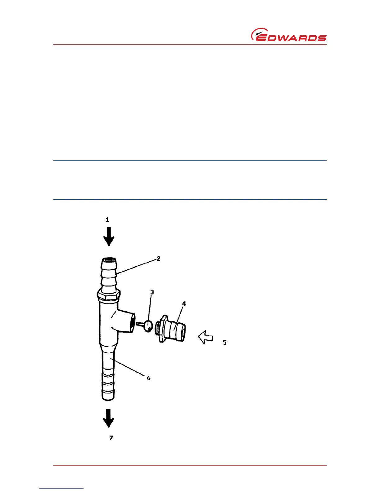
Figure 1 - Model 10 Water Jet Pump
1. Water inlet
2. Jet nozzle assembly (C410-01-001)
3. Ball/Pin assembly (C039-01-010)
4. Vacuum connection (C410-01-004)
5. Vacuum
6. Body (C410-01-005)
7. Water drain