D048-50-880 Issue E
Page 8 © Edwards Limited 2013. All rights reserved.
Edwards and the Edwards logo are trademarks of Edwards Limited.
INSTALLATION
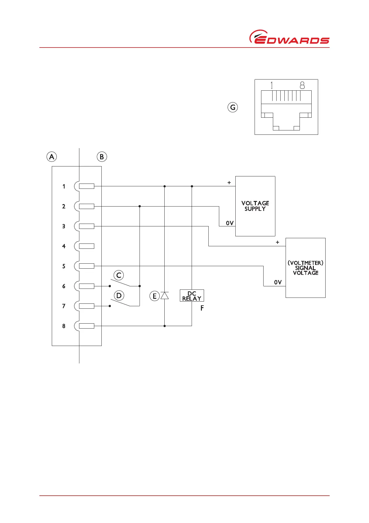
Figure 3 - Schematic Diagram of Recommended Electrical Connections
Connect a switch between pins 7 and 2 to enable and disable the gauge.
Connect a switch between pin 6 and 2 to enable and disable the degas function.
A. AIGX connector (socket)
B. Cable electrical (plug)
C. Degas enable switch
D. Gauge enable switch
E. Back EMF suppression diode (optional)
F. D.C. relay (optional)
G. View of AIGX connector
 Loading...