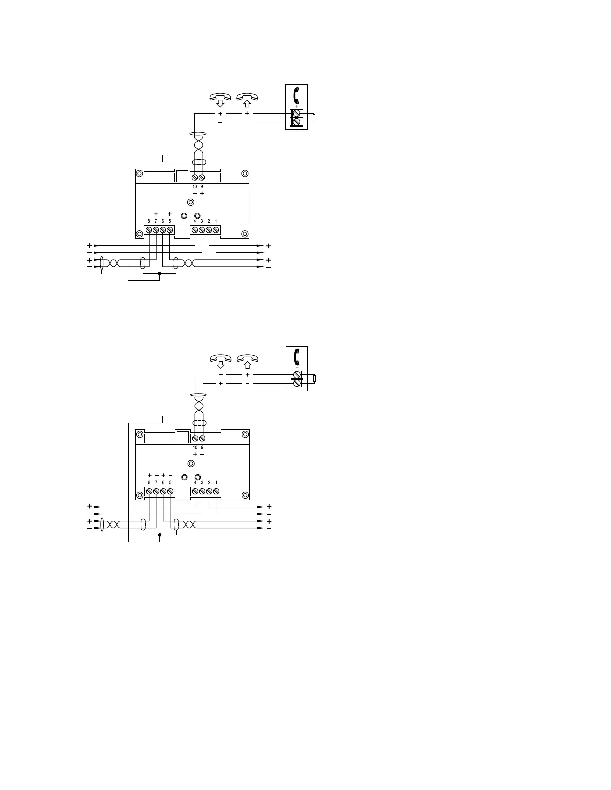
Figure 5: Class B telephone (personality codes 6 and 26)
Three-state telephone circuit (personality code 6)
Four-state telephone circuit (personality code 26)
(1) Telephone circuit. The plus and minus symbols indicate
signal polarity.
(2) Supervised.
(3) Power-limited unless connected to a nonpower-limited
source. If the source is nonpower-limited, eliminate the
power-limited mark and maintain a minimum of 0.25 in.
(6.4 mm) space from power-limited wiring. For other
mounting methods, see enclosure and bracket installation
sheets to maintain separation of power-limited and
nonpower-limited wiring. The wire size must be capable of
handling fault current from nonpower-limited source.
— or —
Use type FPL
, FPLR, FPLP, or permitted substitute cables,
provided these power-limited cable conductors extending
beyond the jacket are separated by a minimum of 0.25 in.
(6.4 mm) space or by a nonconductive sleeve or
nonconductive barrier from all other conductors. Refer to
the NFPA 70 National Electrical Code for more details.
(4) Required if the distance from the GSA-CC1
to the phone is
greater than 5 ft. Shield must be continuous, insulated, and
isolated from ground, except for the connection to chassis
ground in the control panel.
(5) 47 kΩ EOLR (P/N EOL-47).
(6) Signaling line circuit (SLC) to next device.
(7) Telephone riser (to next module or end-of-line supervisory
device).
(8) Use shielded twisted pair. Shields must be continuous and
grounded at the panel end.
(9) Telephone riser (from previous device).
(10) Signaling line circuit (SLC) from previous device.
Supervised and power-limited.
(1)(2)(3)
(10)
(9)
(6)
(7)
(5)
(4)
(3)(8)
(1)(2)(3)
(10)
(9)
(6)
(7)
(5)
(4)
(3)(8)
P/N P-047550-1802-EN • REV 04 • ISS 23JUN15 5 / 6