Do you have a question about the Edwards SIGA-CC2 and is the answer not in the manual?
General notes for wiring the device according to applicable codes and regulations.
Notes specific to riser wiring, including line impedance and survivability requirements.
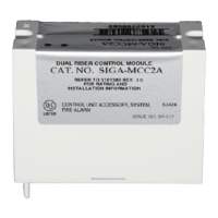
The SIGA-CC2 Dual Input Signal Module is an addressable device designed to connect one of two risers to a Class B supervised output circuit within a fire alarm system. This module acts as a selector, allowing the output circuit to be connected to either Riser 1 or Riser 2 when activated. Typically, Riser 1 is designated for the ALERT channel, while Riser 2 is used for the EVAC (evacuation) channel.
The module's primary function is to provide a supervised output for various notification appliances. When activated, it connects the output circuit to the selected riser, which can supply either 24 VDC for polarized audible and visible signal notification appliances (such as horns and strobes) or 25/70 VRMS for audio evacuation speakers. This versatility makes it suitable for a range of fire alarm system configurations.
A key feature of the SIGA-CC2 is its supervision of the output circuit for open or shorted wiring. If a short circuit is detected, the control panel will inhibit the activation of the signal circuit, preventing the riser from being connected to the wiring fault. This enhances system reliability and safety by preventing potential damage or false alarms due to wiring issues.
It's important to note that the SIGA-CC2 module itself does not provide signal synchronization. For installations requiring horn and strobe signal synchronization to meet UL 864 requirements, a separate Genesis Signal Master module must be installed. Additionally, while the module supervises its output circuit, it does not supervise the riser; this function is handled by the fire alarm control panel.
The SIGA-CC2 module requires two addresses on the signaling line circuit (SLC). These addresses are assigned electronically, eliminating the need for manual address switches. This simplifies installation and configuration.
For installations where the output circuit connects to electromechanical bells or horns, a bipolar transient protector (P/N 235196P) is recommended. This protector safeguards the module from transient spikes that can be caused by switching inductive loads. To ensure optimal protection, bells and horns should be located at least 6 ft. (1.8 m) from the module.
The module is configured using personality codes. Personality code 7, "Riser selector - supervised output (Class B)," configures the SIGA-CC2 as a one- or two-input signal power (24 VDC) or audio evacuation (25 or 70 VRMS) riser selector with a supervised output. This code ensures the module operates as intended for its specified applications.
For maintenance and diagnostic purposes, the SIGA-CC2 module includes diagnostic LEDs that provide visible indications of its state through the cover plate. A green LED flash indicates a normal state, while a red LED flash signifies an alarm or active state. These visual cues allow for quick and easy status checks, aiding in troubleshooting and system monitoring.
Installation of the SIGA-CC2 module should always be performed in accordance with applicable national and local codes, ordinances, and regulations. The module is shipped as an assembled unit and contains no user-serviceable parts, so it should not be disassembled. It requires electrical power to operate, and given that fires can cause power interruptions, additional safeguards should be discussed with a local fire protection specialist.
Wiring instructions emphasize the importance of verifying that all field wiring is free of opens, shorts, and ground faults before connection. Wires should be stripped to 1/4 inch (about 6 mm) from the ends to ensure proper connection and prevent ground faults. Each terminal on the module is limited to a single conductor. Test resistors are supplied with the SIGA-CC2 to prevent trouble signals on unused circuits during installation; these should be removed and a UL/ULC Listed 47 kΩ EOLR installed at the end of the circuit when connecting field wires. The module does not support conventional smoke detectors.
For riser wiring, it's crucial to refer to the installation manual for the specific fire alarm panel to determine maximum line impedance and ensure circuit capacitance does not exceed 0.1 µF. If the riser serves more than one notification zone, installation must comply with NFPA 72 National Fire Alarm and Signaling Code requirements for survivability from fire.
The SIGA-CC2 module is a robust and essential component for managing notification and evacuation signals in addressable fire alarm systems, offering supervised output and flexible riser selection capabilities.
| operating voltage range | 15.20 to 19.95 VDC |
|---|---|
| standby current | 310 µA |
| activated current | 135 µA |
| ground fault impedance | 10 kΩ |
| output rating (24 VDC) | 2 A |
| output rating (25 VRMS audio) | 50 W |
| output rating (70 VRMS audio) | 35 W |
| circuit capacitance | 0.1 µF max. |
| operating temperature | 32 to 120°F (0 to 49°C) |
|---|---|
| relative humidity | 0 to 93%, noncondensing |
| storage temperature range | −4 to 140°F (−20 to 60°C) |
| electrical box minimum size | 3.5 × 3.5 × 1.5 in. (85 × 85 × 38 mm) |
|---|---|
| compatible electrical box depth | 2-1/2 in. (64 mm) |
| compatible electrical box depth with dual-gang cover | 1-1/2 in. (38 mm) |