Do you have a question about the Edwards iXM3000 customer special A and is the answer not in the manual?
Defines warning, caution, and notice symbols and their importance for safe operation.
Details various safety symbols used in the manual and on the equipment for hazard identification.
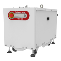
Introduces the iXM dry pumps as low energy, medium duty systems for Etch and PECVD processes.
Outlines the intended applications for the iXM pumping system and warranty implications.
Describes EdCentra for monitoring and data acquisition, and tools for system configuration.
Explains the Green Mode feature for reducing utility consumption during standby.
Provides key technical specifications including dimensions, mass, noise, and performance metrics for various iXM models.
Details the environmental parameters for operating and storing the iXM pumping system.
Lists materials used in contact with pumped gases and their applications within the system.
Presents center of gravity and levelling foot load data for different iXM pump variants.
Specifies requirements for nitrogen supply pressure, quality, and inlet connection for purge operations.
Details electrical supply requirements, protection, mains connectors, and wiring configurations.
Outlines parameters for the water cooling system, including pressure, flow rate, and water quality requirements.
Presents results of tracer gas fugitive emission testing for various process gases according to SEMI S6 Standard.
Highlights critical safety warnings and precautions for installing the iXM dry pump system.
Provides step-by-step instructions for safely unpacking and inspecting the pump system upon arrival.
Guides on selecting a suitable location, positioning, and leveling the system for optimal performance and safety.
Details the process of installing the system, including securing it and connecting electrical supply.
Covers connecting vacuum, exhaust, nitrogen supply, electrical, emergency stop, and cooling water systems.
Advises on installing safety equipment like flow rate measurement for nitrogen purge and system shutdown logic.
Outlines the procedure for initial system setup, power-up checks, and start button operation.
Explains the importance of leak testing after installation to prevent substance leakage and air ingress.
Describes how to configure and use the Pump Display Terminal (PDT) for system control and monitoring.
Details methods for starting the pump using MicroTIM, PDT, or the front panel control.
Explains various shut-down modes (auto, fast, controlled) and how to execute them.
Guides on adjusting the gas ballast flow settings and warning thresholds for the Varimode gas module.
Describes how to adjust system operating temperatures via the PDT for process-specific needs.
Provides instructions for routine visual inspection of system connections, pipelines, and cables.
Explains how warnings are indicated via LEDs and PDT messages, and how to acknowledge them.
Details alarm indications on LEDs and PDT, and the actions required for alarm conditions.
Discusses causes and actions for unplanned system shutdowns due to sensor triggers like temperature or pressure.
Lists and explains system events recorded by the PDT, such as chassis shorts or accessory overloads.
Covers common warnings and alarms generated by the pump and booster inverters.
Emphasizes safety precautions, including PPE, lockout/tagout, and handling hazardous materials.
Provides instructions for safely moving the system for maintenance or decommissioning.
Details the procedure for draining the cooling water system to prevent damage during transport or storage.
Offers guidance on safely transporting the system, including warnings about oil leakage and storage limitations.
Explains the procedure for returning equipment for service, including required forms and documentation.
Lists available disconnect boxes for ensuring SEMI S2 compliance and EMO functionality.
Describes Active and Passive Accessory Modules for expanding system connectivity and functionality.
Details the PDT accessory for pump control, monitoring, and status reporting.
Includes PDT holsters and extension cables for flexible placement and use of the terminal.
Lists seismic restraint bracket options for securing the system against seismic activity.
Describes the nitrogen flow switch assembly used for monitoring flow and as an interlock.
Covers various interface modules like MicroTIM, EMS, and iGateway for tool control and communication.
Lists exhaust check valves and extraction cover kits for managing pump exhaust safely.
Details constant flow water valves for maintaining a set cooling water flow rate.
Describes the water flow monitor assembly that displays water flow rate on the PDT.
| Category | Water Pump |
|---|---|
| Model | iXM3000 customer special A |
| Frequency | 50 Hz |
| Power | 750 W |
| Voltage | 230 V |