Chapter 2: Installation and assembly
LaserSense HSSD-2 Aspirating Smoke Detector Installers Handbook 33
below. In this example, the command module will not be able to monitor the
network for communications problems, but less wiring is required.
Figure 22: Non-fault tolerant serial configuration
(1) Command module
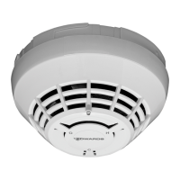
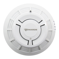
(2) Detector 1
(3) Detector 2
(4) Detector 127
Connecting a command module to an
addressable fire panel
When a command module is being used to manage one or more detectors (the
maximum limit is 127) an Addressable Protocol Interface Card (APIC) is required
to decode detector status information in the command module and convey to the
Fire Panel via the Addressable Bus 1 and Bus 2 terminal block connections (see
“Command module terminal block connections” on page 25 for details). In this
configuration only one interface is required and all detector information is
available through this interface, one address per device.
APICs plug into a connector on the main PCB via a ribbon cable. Once plugged
in, the addressable signaling line circuit (SLC) in and out are connected to the
main PCB addressable bus terminals and the address DIP switches are set to
the SLC address. Refer to the APIC installation sheet for details.
Note: Some addressable protocols may limit the maximum number of device
addresses to less than 127. Some protocols may not support all of the available
alarm levels, and fault reporting is usually a general fault with no detailed fault
information.