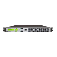
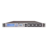
HD490 Smart Encoder
Copyright © 2000-2012 EEG Enterprises, Inc. 38
All Rights Reserved.
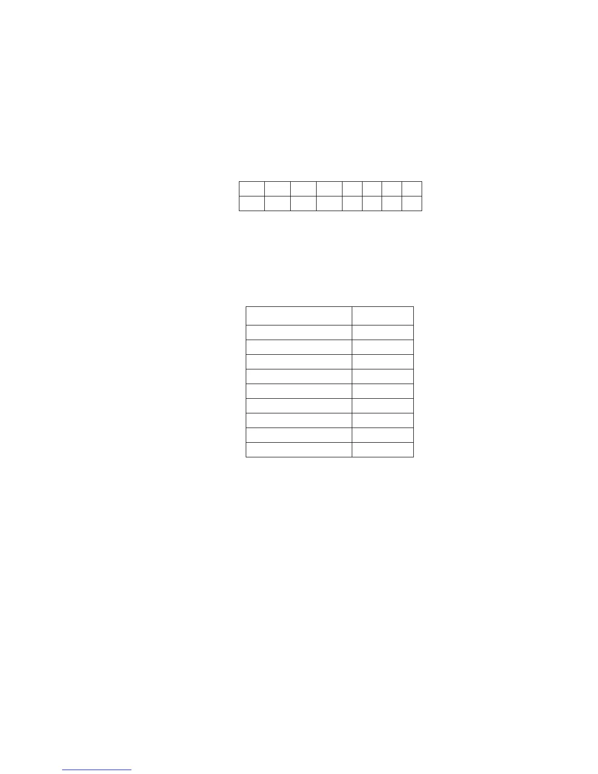
GPIO Connector Pin Numbering
The GPIO pins are located on the two 16-pin connectors on the rear
panel of the HD490. The top connector is used for the GPI switches and
the bottom is used for the GPO switches, with the pins numbered in the
following manner on each connector:
GPI Pin Assignments
The GPIs use the upper 16-pin connector, which mates to a female IDC-
16 connector. The pin assignments are given in the table below: