Electronic device DMU2000 - DMU3000 - DMU3000 PLUS
26
Electronic device DMU2000 - DMU3000 - DMU3000 PLUS
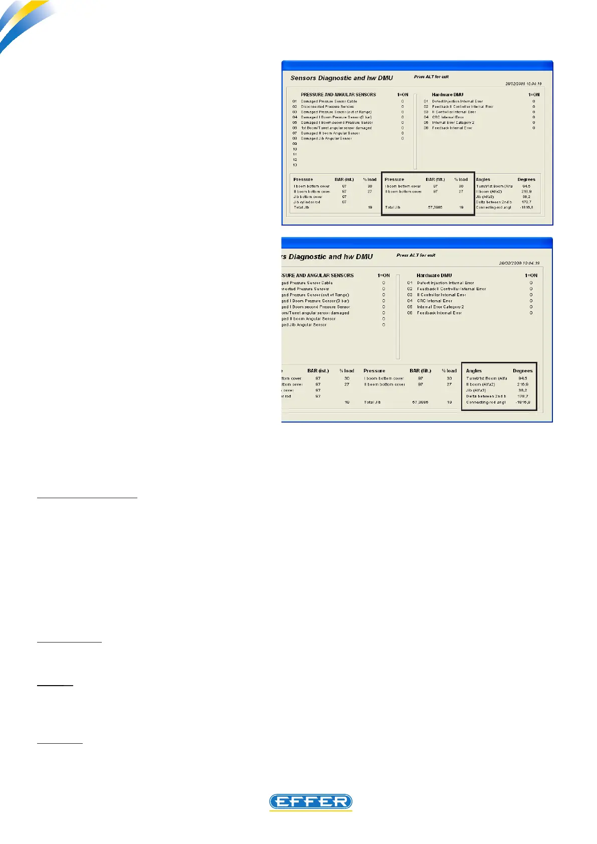
a4) Pressure Bar (filt)
Indicates the pressure value ltered in-
side the various lifting cylinders to which
the pressure sensor is tted.
The lter applied in the software leads to
eliminate the variations in pressure re-
sulting from small structure swingings.
The percentage of load corresponding
to the pressure value is shown nearby.
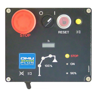
a5) Angles/Degrees
Below is the explanation of highlighted
values within the box:
Tower / 1st boom (alpha 1) : Crane mod-
els fitted with the encoder to detect
the swinging position, the angle of the
column – tower is shown next to this in-
dication with respect to the zero point:
this zero point is located in the centre
of the working area with downgraded
lifting performance (area in front of the
truck cab).
On crane models where the slewing po-
sition is run by micro switches or by proximity switches, the value -247 appears next to the indication
for standard cranes, while if the anti-bridge function or boom height limitation to use the crane with
PLE, is enabled, the angle which the first boom has with respect to the horizontal line, appears.
2nd Boom (alpha 2): If cranes are built in the basic crane conguration, with the second boom without
uplifting, the value that appears on the side of this line is 0 and it is not to be considered (one ON-OFF
angle sensor is tted to the second boom of the crane).
In the case of cranes equipped with additional jib or second boom with uplifting, a proportional angle
sensor is fitted to the second boom, and the value displayed relates to the boom angle with respect to
the horizontal line, with positive / negative sign when the boom is positioned above / below the hori-
zontal line (the crane operation, when the DMU load limiting device comes into operation, is different
whether the second boom is positioned above or under the angle of 30°
Jib (alpha 3) : the value shown is related to angle of additional jib with respect to the horizontal line,
with positive/negative mark when the jib is positioned above/under the horizontal line.
Delta : this box shows the mathematical value concerning the dierence between the values of alpha2
and alpha3. When this value is zero, the additional jib is aligned with the second boom, and the DMU
emits a beep.
Link rod : this box shows the value of the position of the sensor tted to jib, with respect to its horizon-
tality. Note that this has been used for crane setting in prototype phase by Sol.ge technicians.