2322
efgis.com
CPAT FLEX User Manual (ARD4) CPAT FLEX User Manual (ARD4)
4. Physical Installation
See «Modules Physical Installation» sheet for an overview of units assembly, on page 48
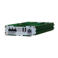
4.1 ARD4 Module Installation
The ARD4 box must be installed inside the vehicle, in a place not directly exposed to the sun.
The support rail must be installed using the rail screws and should be installed in a horizontal
position. The ARD4 will slide into the support rail and a rail stopper will be used on each side
of the unit to keep it securely in place.
The GPS and wireless antennas location may affect the signal’s integrity and should be
installed on the roof on the vehicle clear of any objects.
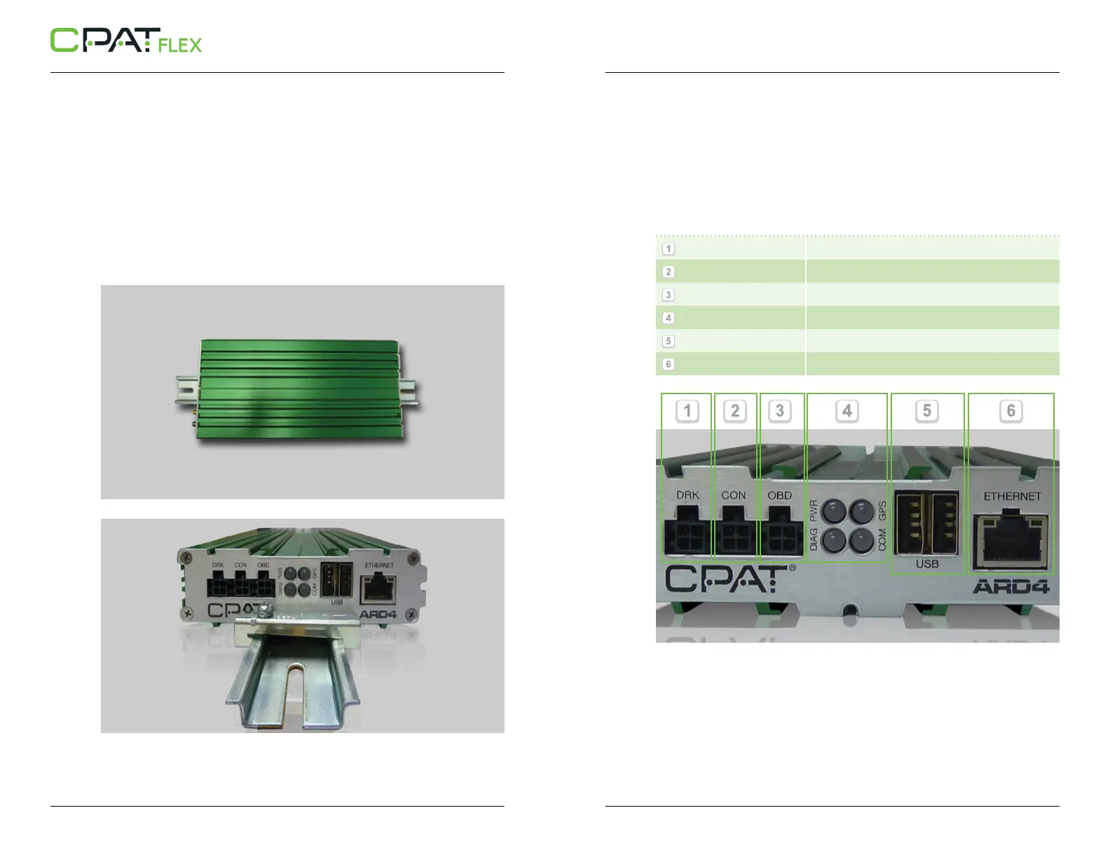
System connectors are located on both sides of the ARD4 unit. The position of each connector,
LED and slot are clearly indicated. Here is a more detailed description of their usage:
// Front panel (From left to right)
- DRK
(Dead Reckoning)
- CON
(Reserved Port)
- OBD
(On-Board Diagnostic)
- Status LEDs
(Power, GPS, Diagnostics, Communication)
- 2 USB Host ports
(USB type A)
- Ethernet
(RJ45 connector)
 Loading...