2726
efgis.com
CPAT FLEX User Manual (ARD4) CPAT FLEX User Manual (ARD4)
CAUTION!
• Never install this product in places where, or in a manner that it could injure
the driver or passengers if the vehicle stops suddenly.
• Never install this product in places where, or in a manner that it may interfere
with the driver’s operation of the vehicle, such as on the oor in front of the
driver’s seat, or close to the steering wheel or shift lever.
• Make sure there is nothing behind the dashboard or paneling when drilling
holes in them. Be careful not to damage fuel lines, brake lines, electronic
components, communication wires or power cables.
• When using screws, do not allow them to come into contact with any
electrical lead. Vibration may damage wires or insulation, leading to a short
circuit or other damage to the vehicle.
• To ensure proper installation, use the supplied parts in the manner specied.
If any parts other than the supplied ones are used, they may damage internal
parts of this product or they may work loose and the product may become
detached.
• It is extremely dangerous to allow the cables to become wound around the
steering column or shift lever. Be sure to install this product, its cables, and
wiring away in such a way that they will not obstruct or inder driving.
• Make sure that leads cannot get caught in a door or the sliding mechanism
of a seat, resulting in a short circuit.
• Please conrm the proper function of your vehicle’s other equipment
following installation of the navigation system.
• Do not install this system where it may (i) obstruct the driver’s vision, (ii)
impair the performance of any of the vehicle’s operating systems or safety
features, including airbags, hazard lamp buttons or (iii) impair the driver’s
ability to safely operate the vehicle.
• Never install the system in front of or next to the place in the dash, door, or
pillar from which one of your vehicle’s airbags would deploy. Please refer to
your vehicle’s owner’s manual for reference to the deployment area of the
frontal airbags.
• Do not install the system in a place where it will impair the performance of
any of the vehicle’s operating systems, including airbags and headrests.
4.1.2 Antennas Installation
The ARD4 comes with two modules, a wireless one chosen by the customer (WIFI or cellular)
and a GPS one. Both the GPS and WIFI (or Cell) antennas must be connected to the ARD4 in
order to maximize sky visibility and data transfer.
4.1.3 Dead Reckoning Installation
The DRK cable is used only with the dead reckoning option.
Green (Speed Signal)
To vehicle speed detection circuit lead coming out of the injection computer.
Brown (Reverse Signal)
To vehicle backup light lead.
4.1.4 On-Board Diagnostic Installation (optional module)
Not available yet.
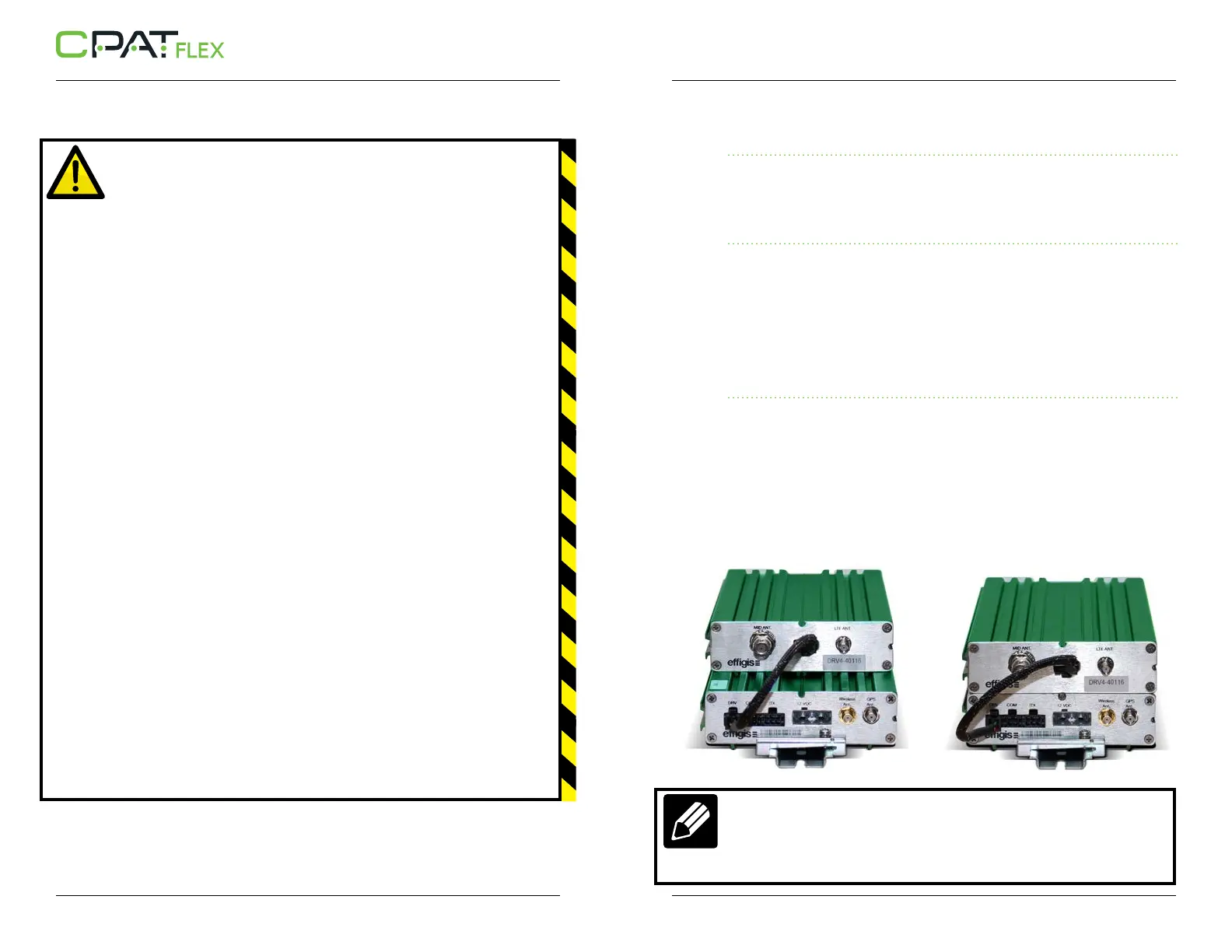
4.2 DRV4 Installation
The DRV4 slides into the ARD4 and a screw is used on both sides to hold the two units in
place.
The wire coming with the DRV4 connects to the DRV connector on the ARD4. (Showed are
the way to slide a DRV4 into an ARD4 and the two units screwed together)
NOTE
The DRV4 unit can also be tied to the ARD4 unit by joining them side-to-side.
The monopole antennas must be connected to the BNC/SMA connectors of
the DRV4.
 Loading...