EFKA AB320A5200
10
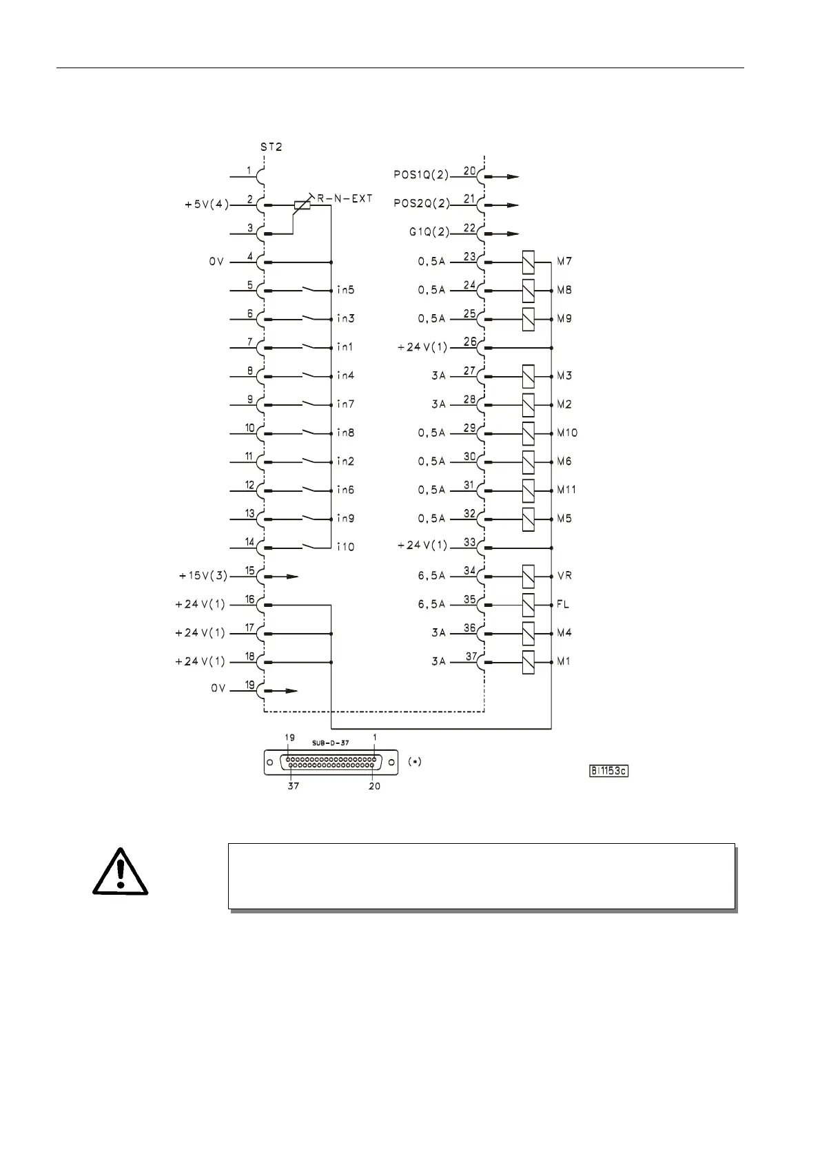
4.3 Connection Diagram
Inputs switched to 0V
in1 - Input 1 i10 - Input 10 M9 - Output 9
in2 - Input 2 M1 - Output 1 M10 - Output 10
in3 - Input 3 M2 - Output 2 M11 - Output 11
in4 - Input 4 M3 - Output 3 FL - Sewing foot lifting
in5 - Input 5 M4 - Output 4 VR - Backtacking
in6 - Input 6 M5 - Output 5 POS1 - Position 1
in7 - Input 7 M6 - Output 6 POS2 - Position 2
in8 - Input 8 M7 - Output 7 GEN - 512 generator impulses
in9 - Input 9 M8 - Output 8 R-N-EXT - External potentiometer for
speed limitation (50kΩ)
ATTENTION!
When connecting the outputs, ensure that a total power of 96VA constant load will not
be exceeded!