EDGER ATTACHMENT — EA0800/EA0800-FC 19
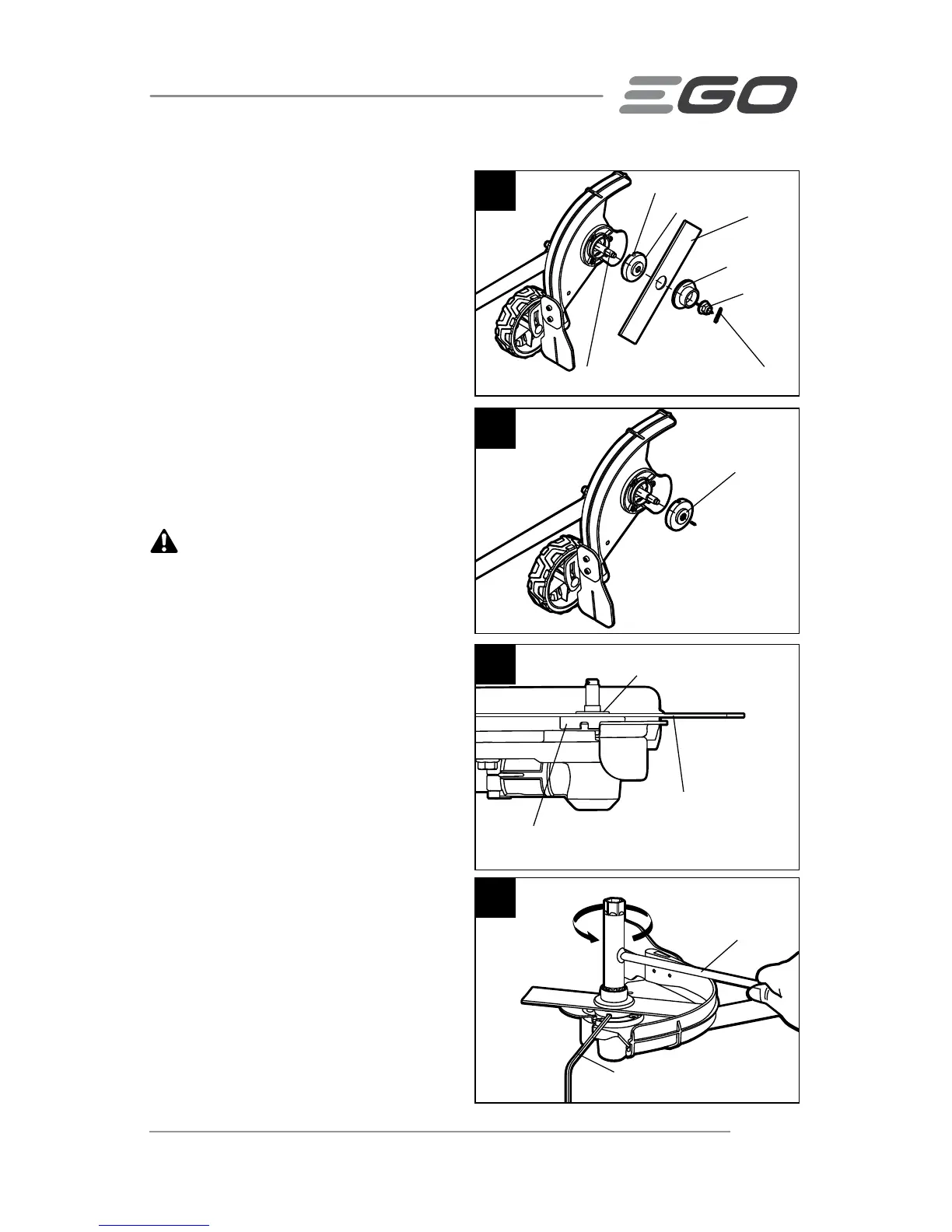
6. Remove the nut, outer flange, blade
and the inner flange from the motor
shaft (Fig. 10). Check and replace
them if they are worn.
Installing the blade
1. Position the inner flange removed in
step 6 of the “Removing the blade”
section onto the motor shaft with
the bulge of the inner flange facing
outwards (Fig.11).
2. Install the new blade onto the inner
flange.
WARNING: The bulge of the inner
flange must engage the blade’s mounting
hole (Fig.12). There should not be any
clearance between the blade and the
inner flange flat surface.
3. Mount the outer flange and the nut
onto the shaft, and pre-tighten the
nut COUNTERCLOCKWISE by hand.
4. Rotate the blade to align the slot in
the flange with the hole in the gear
case (Fig. 8).
5. Insert the hex wrench provided
into the aligned holes to act as a
stabilizer. Use the multi-function
wrench provided to tighten the nut
COUNTERCLOCKWISE securely onto
the shaft (Fig.13).
6. Insert a new cotter pin into the hole
in the motor shaft. Bent the two feet
of the pin in opposite directions with
a needle nose pliers (not included)
(Fig. 8).
13
Stabilizer
Multi-function
Wrench Provided
10
Slot in the Inner Flange
Outer Flange
Nut
Cotter Pin
Inner Flange
Blade
Motor Shaft
11
Bulge Outwards
12
Inner Flange
Blade
Bulge of the inner flange
engaging the blade