10
USER MANUAL LAVC
-
2000
-
D ANAESTHETIC MACHINE
T +49 7461 96 580 0 | F + 49 7461 96 580 90 | export@eickemeyer.com | www.eickemeyer.com
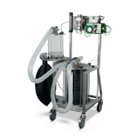
7. PRIMARY COMPONENTS
7.1 Oxygen Flowmeter 0 – 10 l / Min
The fl owmeter delivers oxygen through the vaporizer to the induction chamber and / or patient through a specifi c rate of liters
per minute. The oxygen fl owmeter knob is opened, oxygen fl ows through the vertical tube that is labeled liters per minute.
The fl ow of oxygen causes an indicator (ball) to rise and the fl ow rate is read at the center of the ball. When operating the
fl owmeter, the knob should not be overtightened; doing so will damage the fl owmeter knob.
7.2 Vaporizer
The vaporizer can be either ISOFLURANE or SEVOFLURANE. The fresh gas from the fl owmeter fl ows to the vaporizer to deliver
the indicated amount of anesthetic agent.
Vaporizers have a dial with numbers from 0 – 5 for ISOFLURANE and 0 – 8 for SEVOFLURANE. These numbers represent
volume percent and indicate the concentration in percent delivered at the output of the vaporizer. As with any anesthesia
deliver system, fl ows and percentages may vary somewhat due to varying factors, but with the EICKEMEYER® system you are
assured of having total control and will always be operating within the manufacturers specifi cation guidelines of (± 15 %) of
settings and control. It is extremely important to have EICKEMEYER® confi rm the calibration of the vaporizer yearly.
Vaporizers must be fi lled with the appropriate anesthetic agent. The liquid agent should be poured into the vaporizer fi ll
spout until it reaches the desired level on the vaporizer indicator window. Care must be taken to not overfi ll the vaporizer.
The indicator window will help to prevent overfi lling of the vaporizer and will also indicate when the liquid level is low. All
vaporizers have a drain plug to allow the vaporizer to be drained. This plug is usually in the center of the funnel fi ll device.
Continuous removing of the cap to fi ll the vaporizer may cause the drain plug to become loose and may result in agent
leaking from the drain. The drain plug should be checked periodically to ensure that it is tight.
7.3 Inspiratory Valve
The inspiratory valve allows the fresh gases to fl ow only to the patient and not back to the vaporizer.
7.4 Expiratory Valve
The expiratory valve allows the exhaled gases from the patient to fl ow only into the anesthetic machine and not back to the
patient.
7.5 Absorber Canister
The absorber canister is fi lled with sodasorb or CO₂ absorbent which removes carbon dioxide from the rebreathing circuit. It
is important to change the sodasorb after 12 hours of anesthetic use. The absorber canister on the LAVC-2000-D and LAVC-
2000-D-2 is designed with a drainage system to remove excess moisture.
7.6 Rebreathing Bag
When used during passive setup the rebreathing bag allows the accumulation of fresh and expired gas during exhalation so
that a reservoir of gas is available for the next breath.
7.7 Popoff Valve
The popoff valve is an adjustable pressure limiting valve. The fresh gas fl ow rate is higher than the patient absorption rates,
so the excess gas is removed through the popoff valve and exits the system through the scavenger set up or f / air canisters.
It is very important to keep the valve open or partially open unless positive pressure is being used to infl ate the lungs. If the
valve remains closed, pressure will continue to build in the system. When the Mark 7 is being used this valve must be closed.
7.8 Pressure Manometer
The pressure manometer, located on the Mark 7, is used to monitor the internal pressure within the anesthesia system. The
pressure on the manometer correlates with the same pressure being exerted against the patient’s lungs.