GB
- 18 -
The connection for the water inlet (4) is equipped
with a connector for standard hose coupling sys-
tems. Plug the hose coupling on the supply hose
(min. Ø 1/2“) to the water inlet connector (4).
A backow preventer must be installed between
the water tap and the pressure cleaner! Ask your
local plumber about this.
Remove the transport brace as shown in Figure 5
from the high-pressure hose connector (9). Con-
nect the high-pressure hose (18) to the connector
on the pressure cleaner (9) and to the connector
on the spray gun (14).
You can attach either the normal lance or the
lance with rotating nozzle (Fig. 2) before the pres-
sure cleaner is used.
Solid cone / at fan lance (16)
The shape of the water jet can be changed from
solid cone to at fan by turning the nozzle (Fig. 8).
Lance with rotating nozzle (17)
To remove particularly stubborn dirt, use the lance
with the rotating nozzle (17).
•
Before you connect the equipment to the
power supply make sure that the data on the
rating plate are identical to the supply voltage.
•
If you use any extension cables, make sure
that they are suitable for outdoor use and
have large enough wires:
1 – 10 m: 1.5 mm²
10-30m: 2.5 mm²
•
Insert the power plug (8) on the power cable
(6) into the socket outlet.
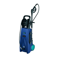
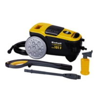
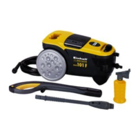
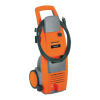
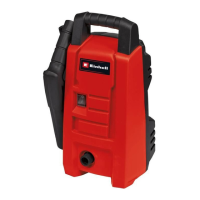
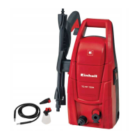
The equipment consists of an assembly with a
pump, which is encased in a shock absorbing
housing. For an optimal working position the
equipment comes with a lance and a non-slip
gun, whose shape and conguration comply with
the applicable regulations.
Once you have completely assembled the pres-
sure cleaner and made all the connections, pro-
ceed as follows:
Open the water inlet. Press safety pin „a“ (Fig. 2)
on the spray gun and pull back trigger lever „b“
(Fig. 2) in order to bleed the trapped air out of the
equipment.
Turn on the equipment by switching the On/O
switch (Fig. 1/3) to “ON”.
To turn o, release the trigger lever (b). The
equipment will then go into standby. As soon as
you press the trigger lever (b) again, the pressure
cleaner will restart.
To turn o the pressure cleaner completely, set
the On/O switch (Fig. 1/3) to “OFF”.
•
Fill the detergent tank (10) with a suitable
cleaning agent.
•
The detergent will be added automatically in
low-pressure mode.
•
Detergent may be used only together with the
following accessories.
Set the solid cone / at fan lance (Fig. 10) to low-
pressure mode (n).
To save space when not in use, the gun and ac-
cessories can be kept in the holder provided.
Anleitung_BT_HP_1435_SPK1.indb 18 28.09.11 19:46