Idle speed of planing knives n
0
: 6500 rpm
Max. planing cross-cutting depth: 3 mm
Max. thicknessing cross-cutting depth: 3 mm
Max. angle of the parallel stop: 45°
Sawdust extractor: Ø 100 mm
Weight: 92 kg
Operating mode S6 40%: Continuous operation with
idling (cycle time 10 minutes). To ensure that the
motor does not become excessively hot it may only
be operated for 40% of the cycle at the specified
rating and must then be allowed to idle for 60% of
the cycle.
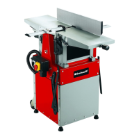
7.1 Technical data of the RT-SP 260
AC motor: 230 V ~ 50 Hz
Power P: 2000 W S1
Protection type: IP40
Vibration a
w
: 12 m/s²
Max. workpiece width 260 mm
Max. workpiece height at thickness opening: 160 mm
Infeed table: 500 x 282 mm
Planing table: 500 x 282 mm
Thicknessing table: 400 x 260 mm
Thicknessing feeding speed: 5 m/min
Idle speed of motor n
0
: 2800 rpm
Idle speed of planing knives n
0
: 6500 rpm
Max. planing cross-cutting depth: 3 mm
Max. thicknessing cross-cutting depth: 3 mm
Max. angle of the parallel stop: 45°
Sawdust extractor: Ø 100 mm
Weight: 92 kg
8. Before starting the machine
n Unpack the surfacing and thicknessing plane and
examine it for any transit damage.
n The machine has to be set up and aligned where
it can stand securely.
n All covers and safety devices have to be properly
fitted before the machine is switched on.
n It must be possible for the planing knife to run
freely.
n When working with wood that has been
processed before, watch out for foreign bodies
such as nails or screws, etc.
n Before you press the ON/OFF switch (1), make
sure that the planing knife is fitted correctly and
that the machine’s moving parts run smoothly.
n Check that the voltage on the rating plate is the
same as your supply voltage before you connect
the machine to the power supply.
9. Assembly
9.1 Fitting the switch/plug unit (Fig. 3)
Fasten the switch/plug unit (25) to the front of the
machine with the two wing nuts (a). You can use
both the upper or the lower two wing nuts (a) to do
so.
9.2 Assembling and fitting the sawdust extractor
(Fig. 4-7)
Assemble and fit the sawdust extractor (5) and
the sawdust extractor hood (28) as shown in
Fig. 4-7. Use the following to do so:
n 5 Allen screws M5 x 12 (a)
n 2 Hex screws M5 x 12 (b)
n 4 washers (c)
n 1 self-locking nut M5 (d) for fastening the sawdust
extractor (5)
9.3 Fitting the hand crank (Fig. 8-10)
Fasten the hand crank (4) to the pin (29) with the grub
screw (b). Then proceed as shown in Fig. 10. Use the
following to do so:
n 1 recessed head screw M5 x 75 (a)
9.4 Fitting the planing table (Fig. 11-13)
Fit the planing table (14) as shown in Fig. 12 and
13.
9.5 Fitting the infeed table (Fig. 15-16)
Undo the Allen screws (c) on the two table guides
(31) and remove them (Fig. 15). If necessary, lever
out the table guides (31) upwards using a
screwdriver. Place the infeed table (13) on the
machine and secure it with the table guides (31) and
the four Allen screws (c) (Figure 16). Then push the
threaded rod of the setting knob for the chip depth
(9) into the infeed table (13). In so doing, turn and
thread the threaded rod of the setting knob for the
chip depth (9) into the female thread of the spacer
roller and fasten with four size M10 (b) nuts. The
greater the distance between the two pairs of locked
nuts, the greater the adjustable chip depth range.
There is a red mark on the threaded rod which
indicates the specified position for the two nuts (b) at
the end of the threaded rod. Finally, fasten the
setting ring (a) as shown in Fig. 19. To do so, use the
notch (e) provided for the grub screw (d) which is
GB
22