_TECNOEKA Srl___________________________________________________________ use and instruction manual _
_ page 10 _________________________________________________________________________________________
3.
3. 3.
3. START
STARTSTART
START-
--
-UP
UP UP
UP (for installation technician)
(for installation technician)(for installation technician)
(for installation technician)
3.1
3.1 3.1
3.1 Check of nominal thermal capacity
Check of nominal thermal capacityCheck of nominal thermal capacity
Check of nominal thermal capacity
The nominal thermal capacity must be verified by an authorised technician or by the gas
supply Body, observing the information in this use manual. This check must be performed for
new installations, adaptation to another type of gas and during all extraordinary maintenance
jobs.
There is no other possibility of adjusting the nominal thermal capacity – this is done by
measuring correct connection pressure and checking if the injector being used is of appropriate
diameter. The nominal thermal capacity is controlled by using a gas meter and a chronometer.
The exact volume of gas that must flow through per time unit can be obtained from the
technical specifications table. This value must be maintained in the specified range, the
permissible tolerance being ±5%.
3.2
3.2 3.2
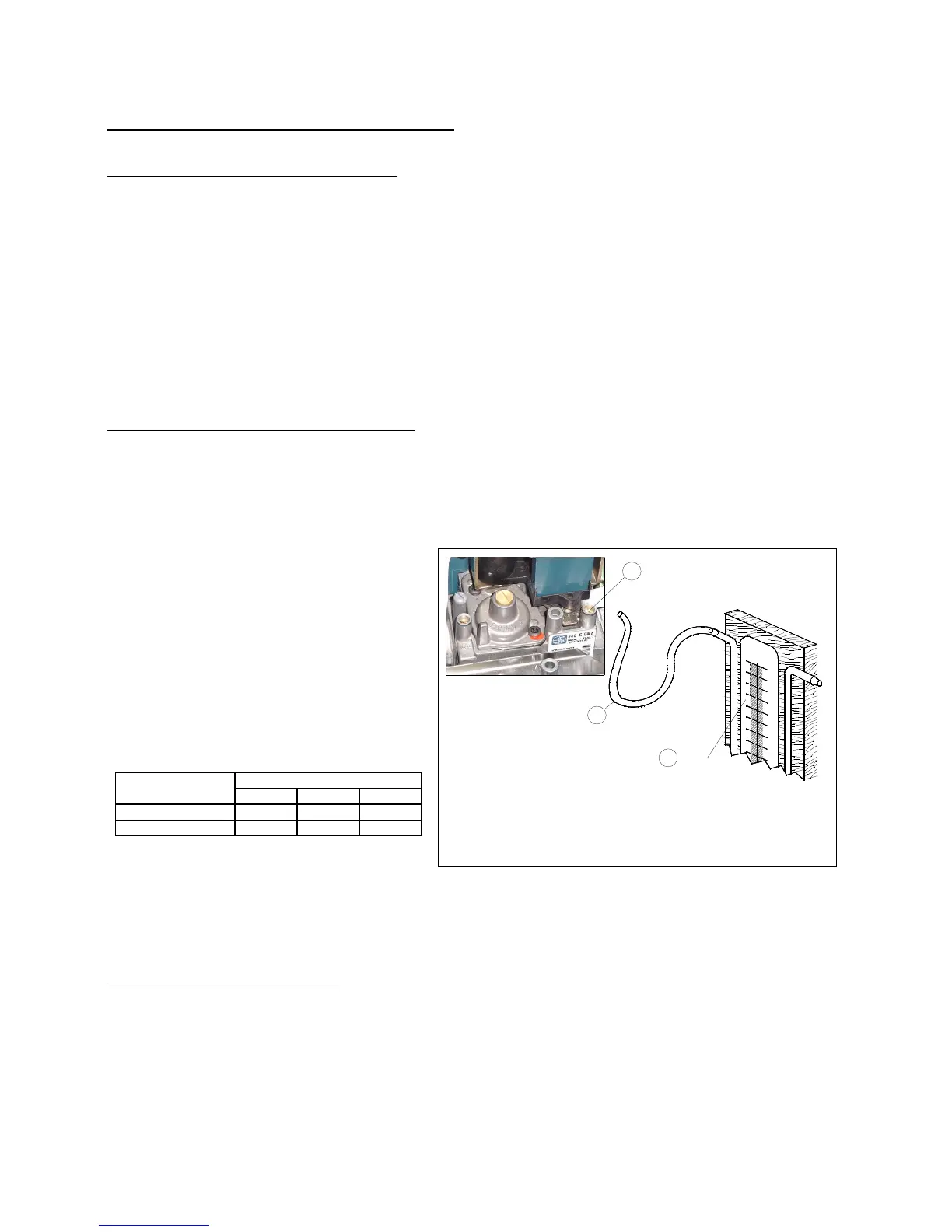
3.2 Check of connection pressure (Fig. 5)
Check of connection pressure (Fig. 5)Check of connection pressure (Fig. 5)
Check of connection pressure (Fig. 5)
Connection pressure is measured while the appliance is operating, using a pressure
measuring device for liquids (for example, a “U” pressure gauge with minimum resolution of
0.1 mbar). Control procedure: connect the hose ”T” of the pressure gauge “M” to the pressure
take-off at entry “P” of the gas solenoid-valve after removing the door on the right of the oven
and the tightness screw of the pressure take-off.
this value is not in the range shown in
table 2 and it cannot be brought within
these values by adjusting the pressure
reducers of the gas supply system,
definitive start-up of the appliance is
quite impossible.
The gas supply Body must be
informed about this.
..
.
Type of gas
Type of gasType of gas
Type of gas
G
GG
Gas
asas
as
pressure
pressurepressure
pressure
(mbar)
(mbar)(mbar)
(mbar)
Normal
NormalNormal
Normal
Minimum
MinimumMinimum
Minimum
Key
KeyKey
Key:
::
:
T =
T = T =
T = Hose
HoseHose
Hose
M = “U”
M = “U”M = “U”
M = “U”
pressure gauge
pressure gaugepressure gauge
pressure gauge
P =
P = P =
P = Pressure take
Pressure takePressure take
Pressure take-
--
-off at entry
off at entry off at entry
off at entry of gas solenoid
of gas solenoidof gas solenoid
of gas solenoid-
--
-valve
valvevalve
valve
Fig. 5
Fig. 5Fig. 5
Fig. 5
After you have measured the connection pressure, disconnect the hose “T” and screw the
tightness screw of the pressure take-off “P”.
3.3
3.3 3.3
3.3 Adaptation to other gasses
Adaptation to other gassesAdaptation to other gasses
Adaptation to other gasses
To adapt the oven to a type of gas that differs from the one tested in the factory (see
technical data plate), replace the injector of the main burner and adjust primary air inflow with
the adjustment bush. To do this, cut off electrical power and remove the door on the right of
the oven in order to facilitate access to the burner and to the primary air adjustment device. If
you do not have the necessary spare parts, contact the manufacturer’s technical assistance
service. Adaptation must be effected by qualified personnel. Consult the technical specifications
in table 1 and 3, and then replace the main injector and adjust primary air.
 Loading...