EKO INSTRUMENTS CO., LTD. - Pyranometer MS-80 - Instruction Manual Ver. 3
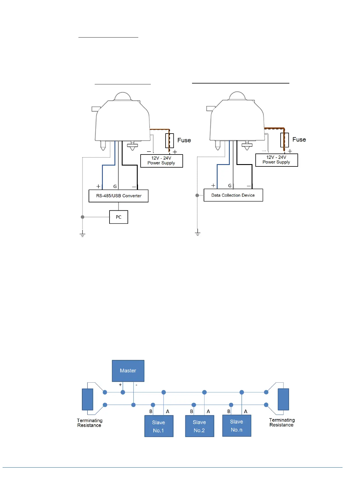
2-3. How to Connect MS-80M (See Table 5-3. Wire Color Codes also)
Connect the output cable end to DC power supply (12-24V), PC or data logging device. For
overcurrent protection, install a fuse (0.5A) in series between DC power supply and MS-80M
connecting wire.
2-4. How to Connect Communication with Modbus RTU
MS-80M can connect to a system that communicates with MODBUS RTU by using RS-485.
Maximum of 100 units can be connected, and individual address can be assigned.
Connection of MS-80M to the RS-485 communication network is shown below.
Master represents the data logging device (such a PC), and slaves represent devices such as
MS-80M.
Connect the + and – for the master to (A/Tx) and (B/Rx) for each MS-80M. Also at the end of
network, connect 120Ω terminating resistance.
*Modbus ID setting is required separately. (See [A-5. Change MS-80M Settings]).
Figure 5-4. Communication Connection with Modbus RTU
Figure 5-3C. How to Connect MS-80M
When Connecting to Data Logging Device
 Loading...