EKO INSTRUMENTS CO., LTD. - Pyranometer MS-80/80S/80U - Instruction Manual Ver. 1
Pg. 17
Installing at an inclined angle
After the MS-80, MS-80S or MS-80U is adjusted to horizontal position in levelled surface, install it on tilted a
tilted mount.
When installing the pyranometer, do not remove the levelling feet or fixed feet. If the levelling
feet are removed, it may induce offsets to output values due to the thermal effects from the
mounting plate.
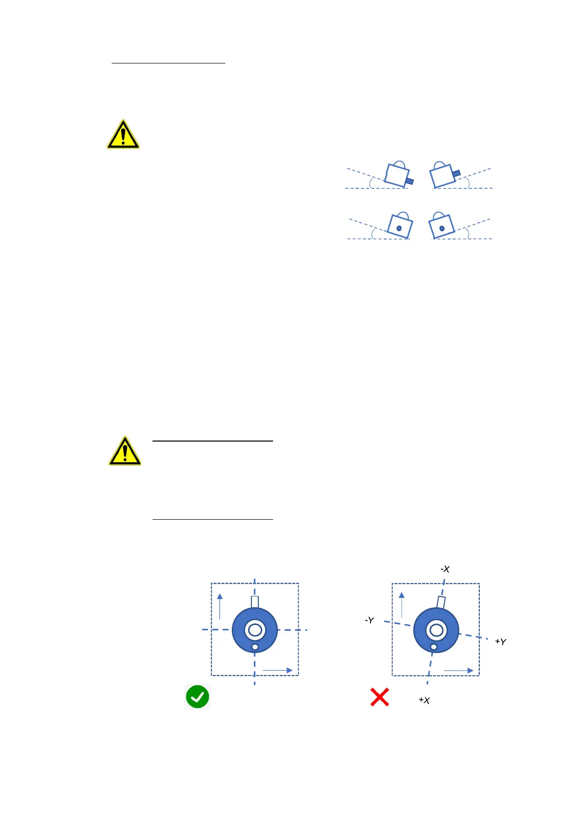
In the case of MS-80S, it is possible to acquire tilt
information obtained from the built-in tilt position
sensor through Modbus RTU. The sensor position
can be measured in two different planes (X,Y).
<Tilt (X axis)> (90º to 0) and (0 to -90º)
<Roll (Y axis)> (90º to 0) and (0 to -90º)
The tilt and roll angles are relative to the calibrated X and Y axis of the sensor and surface mounting plane X’
and Y’. When the sensor is positioned in the same plane X = X’ and Y = Y’, the measured tilt and roll angles
(X and Y) correspond to plane of installation X’ and Y’.
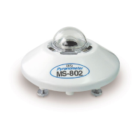
The pyranometer connector is an important reference for setup and corresponds to the X-
axis reference plane.
For setup at horizontal plane: Setup the pyranometer with the signal cable connector facing
the nearest Earth’s pole. In the Northern hemisphere, the connector should be orientated
North, in the Southern hemisphere, the connector should be orientated South. If the cable is
not oriented to the nearest pole, it does not affect the angle measurement. The angle
measurement reflects the tilt and roll of the corresponding sensor position.
For setup at inclined plane: Setup the pyranometer with signal cable aligned with the
installation platform (X’, Y’), see figure 5-3B. When the sensor is not aligned, the tilt (X) and
roll (Y) measurement does not reflect the angle X’ and Y’, see figure 5-3C.
4) Fasten the pyranometer to the base with the 2 bolts [included] and put the sunscreen back on the pyranometer.
+Y
-X
X’
Y’
-Y
+X
X’
Y’
Figure 5-3B Tilt and roll angle
corresponding to reference plane
Figure 5-3C Tilt and roll angle not
corresponding to reference plane
Figure 5.3A Tilt angle (-90 to 0º) and (0 to 90º)