EKO INSTRUMENTS CO., LTD. - Pyranometer MS-80/80S/80U - Instruction Manual Ver. 1
Pg. 24
Datalogger connection (Modbus)
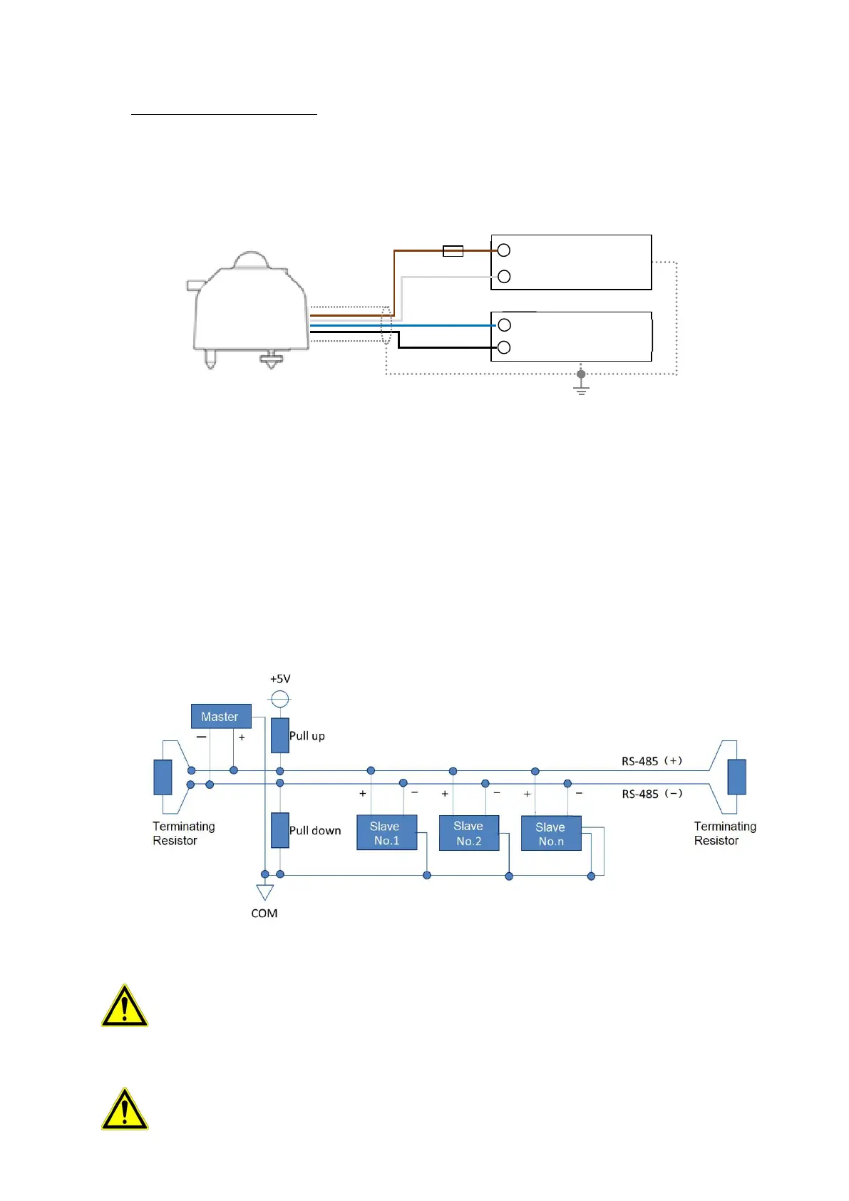
Connect the 4 wires of the sensor cable with the corresponding wire color to the RS-485 communication port of the
datalogger master and power supply unit (figure 5-11). Connect the power terminals to a DC power supply [8 to 30
V]. We recommend to use a fuse [0.5A] to the DC power supply line [+] for over current protection.
MS-80S can be configured within a multi sensor RS-485 Modbus communication network. Up to 31 sensors per
one Master can be connected and be assigned with a unique address. For a multiple sensor network the sensors
need to be configured according to the recommended RS-485 configuration standards as shown in figure 5-12.
The master represents the data-logging device and slaves represent devices such as MS-80S or other serial
devices in the same network. Connect the communication wires of the slave to the modbus communication input of
the master. Connect a 120Ω termination resistor at the end of the communinication line. The master device may
have an integrated termination resistor and pull-up and pull-down resistors. If any communication issues occur,
apply those separately.
Figure 5-12. Communication Connection with Modbus RTU
Apply a Termination resistor (typically 680 to 850Ω) : Typically reflections occur on long lines, resulting
in a receiver misreading logic levels. Proper termination prevents reflections, improving data integrity.
Apply Pull-up and pull-down resistors (typically 120 to 150Ω): Necessary to keep the voltage level
constant when the transmission line is in a high impedance state.
Communication errors may occur depending on the connection distance and the number of
connections. In that case, please prepare and apply a RS485 booster or a repeater.
Fig. 5-11. How to connect MS-80S (Modbus RS-485)
Brown
White
Blue
Black
Shield
Power supply
DC8 to 30V
Data logger
RS-485 Modbus
Fuse [0.5A]