EKO INSTRUMENTS CO., LTD. - Pyranometer MS-80/80S/80U - Instruction Manual Ver. 1
Pg. 26
4. Overview wire assignments
Table 5-7. Wire Color Codes of MS-80 and MS-80U (Also see [7-3. Output Cables])
Table 5-8. Color Codes of cable of MS-80S
[*] When selecting 0-1V output, a precision resistor is required separately.
No.
Cable Color
MS-80 MS-80U
MS-80 MS-80U
1. Brown Red mV [+] mV [+]
2. White White mV [-] mV [-]
3. Blue Green Pt100 [B] NTC
4. Black Black Pt100 [B] NTC
5. Gray - Pt100 [A] ---
Shield Shield Shield FG FG
No. Wire Color 4-20mA Modbus SDI-12 0-1V [*]
1. Brown (+) 8 to 30VDC (+)
5 to 30VDC (+)
12VDC (+) 8 to 30VDC (+)
2. White (-)
4~20mA (-)
/ GND
Vcc GND
/ RS485 GND
Vcc GND
0~10mA (-)
/ 0-1V (-) / GND
3. Blue (+) --- RS485 (+) SDI-12 Data (+)
---
4. Black (+) --- RS485 (-) --- ---
5. Gray (+) 4~20mA (+) --- ---
0~10mA (+)
/ 0-1V (+)
Shield Shield FG FG FG FG
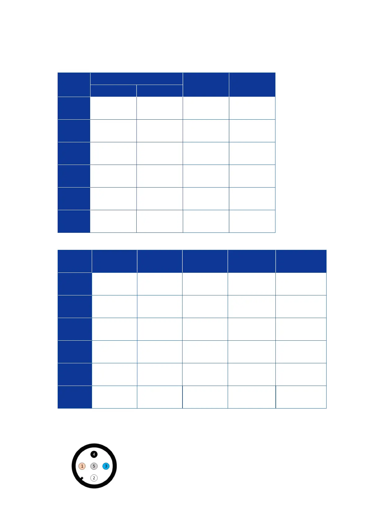
Figure 5-15. Connector pin number of MS-80 and MS-80S
Each number corresponds to the number in Table 5-7 and
Table 5-8. There is no corresponding figure for MS-80U
because the cable can’t be removed from MS-80U body.