EKO INSTRUMENTS CO., LTD. - Pyranometer MS-80/80S/80U - Instruction Manual Ver. 1
Pg. 38
[1]
When the instrument is used in the ambient temperature exceeding the accuracy assurance temperature range,
the measurement error may increase.
[2]
The operational maximum irradiance is defined as the maximum irradiance exposure level. Beyond this point
damage may occur to the sensor.
[3]
When using MS-80, please refer to the product label and check whether it corresponds to NTC or P100.
[4]
Temperature sensor is internally connected to Modbus electronics.
[5]
When 4-20mA is 0 to 1600W・m
-2
, 0-10mA/0-1V : 0 to 1600W・m
-2
.
(default)
[6]
Sensor setting can be changed by connecting the sensor to a PC (Use the USB cable for MS-80S (option) and
download the free configuration software from the EKO website.
Table 7-3. Power consumption supply Voltage specific
5V DC 12V DC 24V DC
Remarks
During
stand-by
75mW
(Approx. 15mA)
90mW
(Approx. 7.5mA)
110mW
(Approx. 4.5mA)
-
Modbus RS-485
170mW
(Approx. 34mA)
180mW
(Approx. 15mA)
190mW
(Approx. 8mA)
Peak value during
communication
4-20mA
output
-
300mW
(Approx. 30mA)
640mW
(Approx. 27mA)
Apply the shunt resistor 250 Ω
and 20mA output
0-1V output
300mW
(Approx. 30mA)
640mW
(Approx. 27mA)
Apply the shunt resistor 100 Ω
and 10mA output
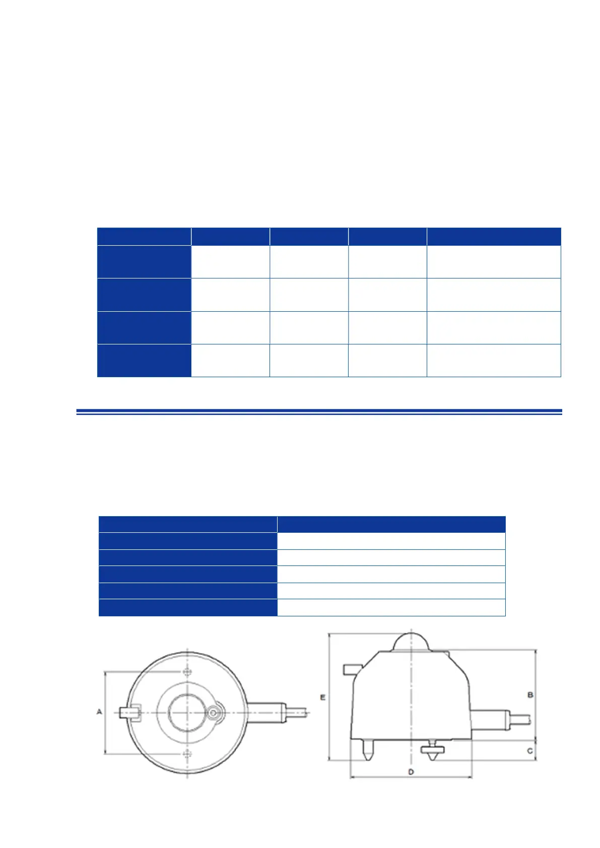
7- 2. Dimensi ons
1. MS-80 / MS-80S
Table 7-3. Dimensions [MS-80 / MS-80S]
MS-80 / MS-80S
A. Fixing Hole Pitch 65 mm
B. Body Height 73 mm
C. Levelling Screw Height 16 mm
D. Width [including Sunscreen/Cover] Φ96 mm
E. Overall Height [approx.] 101mm