Do you have a question about the ekwb EK X Series and is the answer not in the manual?
Product intended for expert users; installation by qualified technician recommended to avoid damage.
EKWB not liable for consequential damages from errors or omissions in instructions or product defects.
24-month warranty against defects in materials or workmanship, with specific return and usage conditions.
EKWB not responsible for assembly not made per instructions; follow manufacturer guides for components.
Verify all necessary parts and tools before installation.
Essential pre-installation advice and warnings.
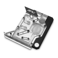
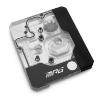
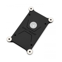
Mount the CPU block, including plate replacement and TIM application, for efficient heat transfer.
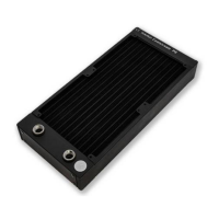
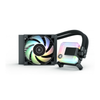
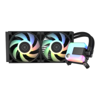
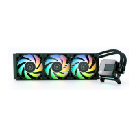
Mount the radiator, pump, and reservoir components using appropriate mounting plates.
Route tubing, connect components, fill with coolant, and conduct a 24-hour leak test.
Details on the water block's compatibility with modern Intel and AMD desktop socket types.
Clean CPU surface and apply thermal compound using recommended methods for optimal cooling.
Install the waterblock on the CPU by tightening nuts in a cross pattern for even pressure.
Mount the radiator and fans inside the PC case, optimizing airflow for cooling.
Mount the radiator on the exterior rear of the case using a specialized holder for space efficiency.
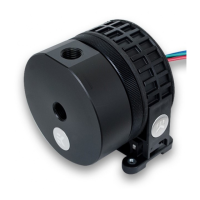
Mount the pump/reservoir unit using a 120mm fan mounting plate, ensuring correct pump height.
Mount the pump on a 3.5" drive bay adapter tray, positioning it for adequate clearance.
Secure the reservoir using mounting clamps, ensuring proper height relative to the pump's inlet.
Review the water loop diagram to understand the flow path for correct tubing installation.
Measure, cut, and install tubing onto fittings, securing them properly for a leak-free connection.
Connect pump and fan cables to the motherboard and power supply using provided adapters.
Prepare coolant mixture and fill the reservoir, leaving space for air bleeding.
Run pump to bleed air, cycle power to speed up process, and ensure system is leak-free for 24 hours.
Connect remaining PC components after successful leak testing and remove the ATX bridging plug.
Cover hardware with towels and place a container under ports before unscrewing fittings.
Gently pull tubes, direct coolant into container, and blow into tubes to drain the system.
| Manufacturer | EKWB |
|---|---|
| Connection Size | G1/4" |
| Dimensions | Varies by model |
| Weight | Varies by model |
| Product Category | Water Cooling |
| Socket Compatibility | Intel LGA 1150, 1151, 1155, 1156, 2011, 2011-3, 2066; AMD AM4 |
| Material | Nickel-plated copper, Acetal |