09/2018 - Art. Nr. 4200 1092 1400A 17
Overview
Contents
Page
Overview Contents..................................................................17
Important notes.......................................................17
Burner description...................................................18
Operation MB-ZRDLE gas train............................................... 19
Automatic combustion control unit..........................20
Allocation chart, connection socket......................... 21
Operation, safety functions .....................................22
Assembly Burner assembly, burner installation position .........23
Gas connection, installation location....................... 23
Liquefied Petroleum Gas, electrical connection ..... 24
Commissioning Checks before commissioning................................25
Ionisation current measurement ............................. 25
Adjustment data, air regulation...............................26
Setting the burner ..............................................27-28
Setting the air pressure switch................................ 29
Setting the gas pressostat, operating check...........29
Service Maintenance ...........................................................30
Troubleshooting ...................................................... 31
Important notes
VG 1.105 D E burners are designed for
the low-pollutant combustion of natural
gas and Liquefied Petroleum Gas. The
design and function of the burners
comply with standard EN676. They are
suitable for use with all heat generators
complying with EN 303 or for use with hot
air generators complying with DIN 4794,
and DIN 30697 within their respective
performance range. Use for any other
application requires the approval of
ELCO. Assembly and commissioning
must be carried out only by authorised
specialists and all applicable guidelines
and directives must be observed.
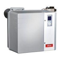
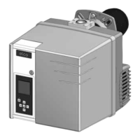
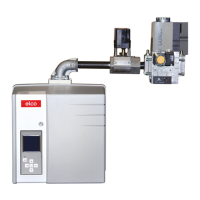
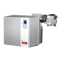
Burner description
The VG 1.105 D E are two-stage, fully
automatic monoblock type burners. The
special design of the burner head
provides low-polluting combustion with
high efficiency. In line with testing as
defined by EN676, the values comply
with emissions class 3 - the most
stringent standard - and also fulfils the
requirements of national environmental
legislation:
AT: KFA 1995, FAV 1997
CH: LRV 2005
DE: 1.BImSChV
NL: EN676, emission class 3
Emissions values may differ, depending
on combustion chamber dimensions,
combustion chamber load and the firing
system (three-pass boilers, U-fired
boilers). For specifying warranty values,
the conditions for the measuring
equipment, tolerances and humidity must
be observed.
Scope of delivery
The burner packaging also contains:
1 gas connection flange
1 compact gas train with gas filter
1 Burner flange with insulation
1 bag containing installation fittings
1 bag containing Technical
Documentation
The following standards should be
observed in order to ensure safe,
environmentally sound and energy-
efficient operation:
EN 676
Forced-draught gas burners
EN 226
Connection of vaporising oil and forced-
draught gas burners to the heat
generator
EN 60335-2
Safety of electrical equipment for
domestic use
Gas lines
When routing gas lines and trains,
observe the general installation
regulations and directives as well as
national guidelines:
CH: - SVGW gas directives G1
- EKAS Form.1942 Liquefied
Petroleum Gas- directive, part 2
- Regulations on cantonal
instances (e.g. fire department
regulations)
DE: - DVGW-TVR/TRGI
Place of installation
The burner must not be used in rooms
exposed to aggressive vapours (e.g.
hairspray, tetrachloroethylene or carbon
tetrachloride), large amounts of dust, or
high levels of air humidity (e.g. in laundry
rooms). An air inlet must be present with:
DE: up to 50 kW: 150 cm
2
per additional kW: + 2.0 cm
2
CH: QF [kW] x 6= ...cm
2
; but at least
200 cm
2
.
Variations may arise as a result of local
regulations.
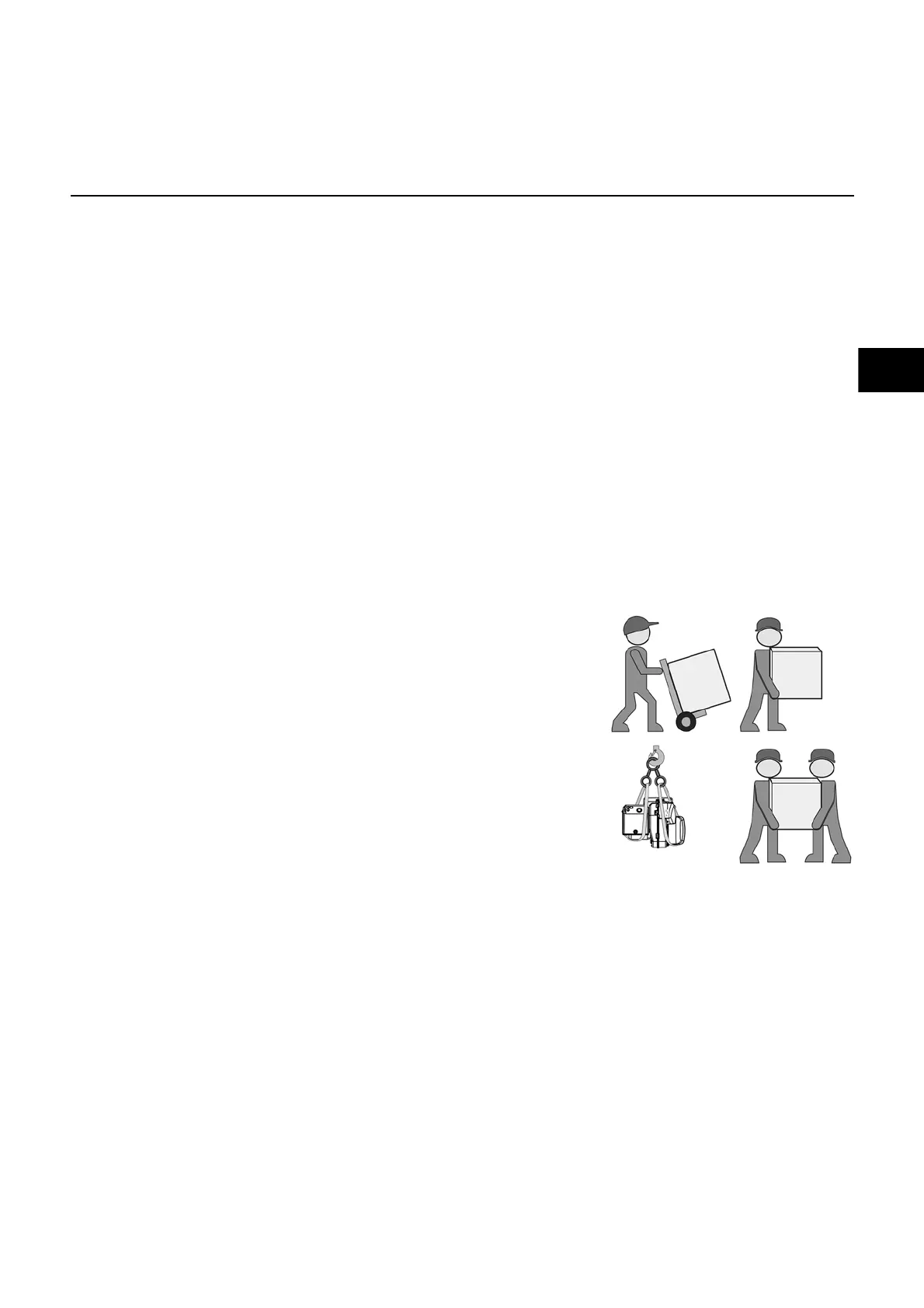
Packaging and handling
• Move the burner still in its packaging
using a trolley or forklift, taking care not
to drop it and elevating it no more than
20cm from ground level. After having
removed the packaging, check that the
contents are in good condition and cor-
respond with what was ordered. If in
doubt, contact the manufacturer. If the
weight and dimensions do not allow for
manual lifting, ask another operator for
help or use a forklift, harness the
burner using belts if no eyebolts are
available.
We can accept no warranty liability
whatsoever for loss, damage or injury
caused by any of the following:
- Inappropriate use.
- Incorrect assembly or repair by the
customer or any third party, including
the fitting of non-original parts.
Provision of the system and the
operating instructions
The firing system manufacturer must
supply the operator of the system with
operating and maintenance instructions
on or before final delivery. These
instructions should be displayed in a
prominent location at the point of
installation of the heat generator, and
should include the address and
telephone number of the nearest
customer service centre.
Notes for the operator
The system should be inspected by a
specialist at least once a year. It is
strongly recommended to take out a
service contract to guarantee regular
servicing.
 Loading...