09/2018 - Art. Nr. 4200 1092 1400A26
Commissioning
Adjustment data
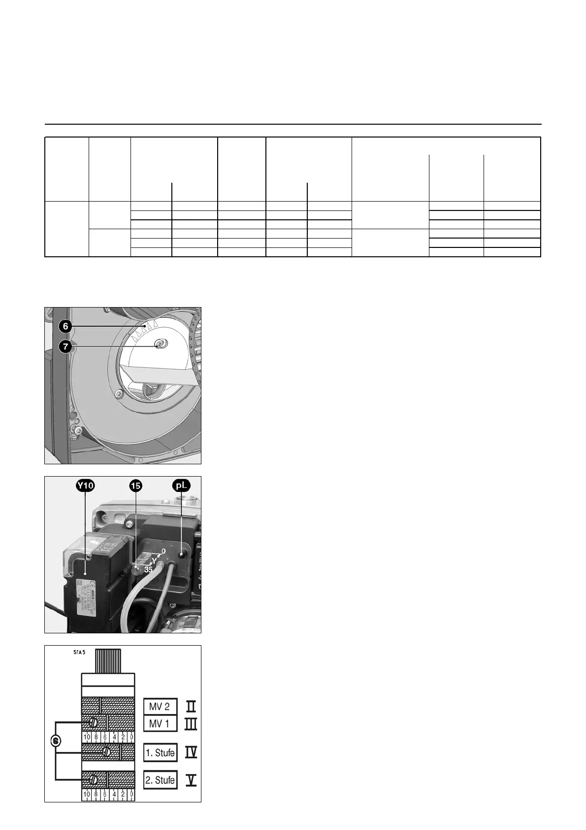
Air regulation
The air intake adjuster 6 is set at the
factory to 1.
Position 1 = max. blower pressure
Position 5 = min. blower pressure
In cases where a higher blower pressure
proves a disadvantage, e.g. large
negative pressure in the combustion
chamber, the pressure can be reduced
by adjusting the air intake adjuster:
• Loosen adjustment screw 7
• Set air intake adjuster to the new value
• Tighten the screw again.
The adjustment data listed above are the default settings. These adjustment values are normally suitable for commissioning
the burner. Always check the adjustment values on a case by case basis. System-specific corrections may be necessary.
Air is regulated at two points:
- On the pressure side of the ventilator
via an air metering drum
- In the burner head via the baffle plate
and burner pipe.
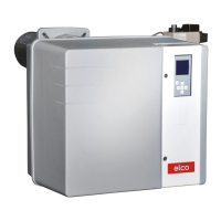
The air metering drum has a linear
regulating characteristic and is operated
by turning regulating actuator Y10. The
value set can be checked on the
graduated scale.
The regulation of air in the burner head
influences not only the airflow but also
the mixing zone and the air pressure in
the burner head. Turn screw 15
- clockwise = less air
- anti-clockwise = more air
The position of the baffle plate can be
controlled on dial Y.
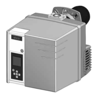
S Cam adjusting screw
II 2d stage solenoid valve control
(MV2)
III 1st stage solenoid valve control
(MV1)
IV 1st stage air damper setting
V 2d stage air damper setting
Setting the cams
Screws S are used to adjust the cams
Turn to the right = more air
Turn to the left = less air
Warning!
For the setting of the cams on more,
more air, the air damper reacts immedi-
ately. For the setting on less, less air, the
air damper takes its new position only
after a restart of the burner or a
switching on part-load or full load. The
cams II and III are connected to each
other (release of gas full load) and must
be between the position of cams part-
load and full load.
Servomotor adjust range: 160°
(between graduations 2 and 18).
Don’t set the air flap below 20°
Gas pressure switch
(factory setting)
Gas pressure
1st stage
PG1
PG
1st stage 2nd sta ge
1st stage
Cam IV
2nd stage
Cam V
mbar mbar mbar
45 60 15 2 8 3,4 5,8
55 72 25 6 13 4,8 7,9
55 84 30 6 18 4,3 9,3
45 60 15 2 8 4,7 7,2
55 72 25 6 13 6,3 10,3
55 84 30 6 18 6,2 13,2
VG1.105 D E
G20
/ G25 10
G31 (1)
Type of gas Burner power
Dimension Y
(mm)
Air flap position
Gas manifold setting