09/2018 - Art. Nr. 4200 1092 1400A 21
Operation
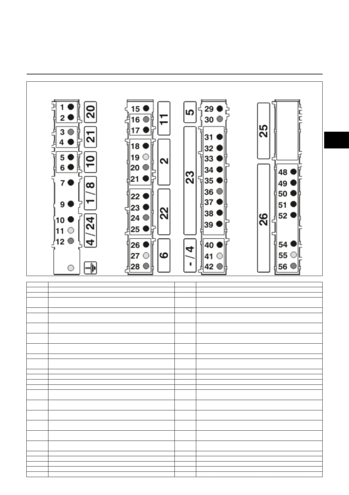
Allocation chart
Connection socket
Terminal
Designation
Terminal
Designation
1 Terminal A of the control unit 29 Terminal 3 of the control unit
2 Terminal 9 of the control unit 30 Neutral
3 Neutral 31 Terminal T7 on the Wieland connector 4P. (1 of the SM
connector)
4 Terminal B of the control unit 32 Terminal C of the control unit (2 of the SM connector)
5 Terminal 4 of the control unit 33 Terminal T1 on the Wieland connector 7P. (3 of the SM
connector)
6 Terminal 7 of the control unit 34 Terminal B5 on the Wieland connector 4P. (4 of the SM
connector) and live of valve 2
7 Terminal T2 on the Wieland connector 7P. 35 Terminal B4 on the Wieland connector 7P. (5 of the SM
connector) and live of valve 1 (terminal 5 of the control unit)
9 Terminal 9 of the control unit via bridge (or temperature
regulator) of regulator
36 Neutral (6 of the SM connector)
10 Terminal 4 of the control unit 38 Terminal 4 of the control unit (8 of the SM connector)
11 Earth 39 Terminal T8 on the Wieland connector 4P. (terminal 9 of
the SM connector)
12 Neutral 40 Live
15 Terminal 2 of the control unit 41 Earth
16 Neutral (terminal 8 of the control unit) 42 Neutral
17 Terminal 9 of the control unit 48 Terminal T8 on the Wieland connector 4P.
18 Terminal B5 on the Wieland connector 4P and terminal 4 of
the SM connector (2nd connector)
49 Terminal T6 on the Wieland connector 4P.
19 Earth 50 Terminal T7 on the Wieland connector 4P. (1 of the SM
connector)
20 Neutral 51 Terminal T2 on the Wieland connector 7P. via the gas
pressure switch
21 Terminal 5 of the control unit and terminal B4 on the Wieland
connector 7P. (1st connector)
52 Terminal 9 of the control unit
22 Terminal 5 of the control unit and terminal B4 on the Wieland
connector 7P. (meter of 1st connector)
54 Live
23 Terminal B5 on the Wieland connector 4P and terminal 4 of
the SM connector (meter of 2nd connector)
55 Earth
24 Neutral 56 Neutral
25 Live
26 Live
27 Earth
28 Neutral
Terminal
Terminal Terminal Terminal
Connector
No.
Connector
No.
Connector
No.
Remote
unlocking
Display
Malfunction
Gas pressure
switch
Burner motor
Power supply L1 Flame monitorSolenoid valve IIOperating hours counter
Continuous
ventilation
IgnitionServomotor
Regulator
Air pressure
switch
Connector
No.
 Loading...