EasyManua.ls Logo

ELCOS CAM 684 - User Manual

Default Icon
12 pages
Print Icon
To Next Page IconTo Next Page
Loading...
ELCOS- Parma- Italy - GB - CAM -684 1
Valid for firmware revisions higher than or equal to 1.24
CONTROL UNIT FOR GENERATING SET
TYPE CAM-684
Made for the preparation of automatic emergency intervention switchboards.
This controls and commands the genset unit. It commands the mains and generator contactors to
supply the user.
MAINS GENERATOR
INSTRUCTION AND USE MANUAL
It is equipped with display to show
the INSTRUMENTS:
- three mains voltmeters
- three generator voltmeters
- delta voltages phase/phase
- star voltages
- three mains/generator ammeters
- frequency meter
- wattmeter total and per phase
- varmeter
- voltammeter
- kilowatt-hour
- cosphimeter per phase
- partial hour-meter
- total hour-meter
- starting counter
- starting failure counter
- tachometer
- battery voltmeter
- battery charger current
(with battery charger type CBS)
- fuel level gauge
- water oil thermometer
- oil pressure gauge
Automatic supervision of faults with messages on the display
Texts in 6 languages: Italian, English, French, German, Spanish and Portuguese
Information on 4 programmable preventive maintenance operations with display of the hours
remaining before the maintenance work is due
Remote controls (starting, stop and test)
EJP function
Preheating glow plugs management
Management of refuelling of working tank from storage tank
Clock to program starting or stopping the generating set
Generator start/stop on request for power
Possibility of starting the generating set in case of low battery-charge
Programmable weekly selftest.
Available inputs for fully programmable anomalies (times, polarities, stopping possibility and message
about the anomaly)
Three-phase voltmetric control, voltage failure, undervoltage, overvoltage, asymmetryc voltage and
not correct phase sequence of the mains and of the generator.
Anomaly historical log (including data from the last 50 occurred anomalies)
Displaying of the most serious faults with both led and messages on the display
Possibility of password protected programming.
CAN Bus Connection (SAE J1939)
Serial ports RS232 and RS485
Connection with a remote panel (Type PRE-685) to display the instruments and errors managed
by the CAM-684
GSM Modem (to be mounted externally), possibility of displaying the control unit instruments with a
mobile phone, operating the starting and stopping and notifying with an SMS message when the
generating set is in alarm state
MODBus protocol through port RS232, RS485 and the serial port via USB
Remote operation with personal computer (on request):
- reading of the instruments shown on the display of the control unit
- anomaly historical record
- displaying of anomalies and operating status of the generating set.
- start stop controls
MODES OF COMMUNICATION OF CAM-684
®
PARMA
ITALY
E-mail: info@elcos.it - HTTP://www.elcos.it
Fax +39 0521/270218
Tel. +39 0521/772021
Question and Answer IconNeed help?

Do you have a question about the ELCOS CAM 684 and is the answer not in the manual?

Summary

Control Unit CAM-684 Overview

Instruments

Lists all instruments displayed by the control unit.

Modes of Communication

Details communication protocols like CAN Bus, RS232, GSM, MODBus.

Key Features

Highlights automatic supervision, multi-language support, remote controls, and maintenance.

Technical Data

Electrical Specifications

Covers supply voltage, self-consumption, and insulation ratings.

Measurement and Accuracy

Details accuracy for various instruments like voltmeters, ammeters, frequency.

History of Revisions

Records changes and firmware updates to the control unit.

Brief Instructions and Interface

Control Unit Interface

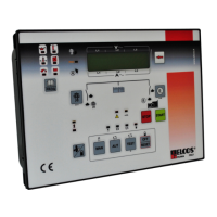
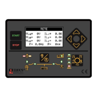
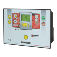
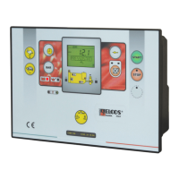
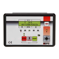
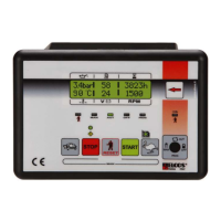
Explains the function of buttons and display elements.

Detailed Instrument Descriptions

Provides detailed explanations for each instrument shown on the display.

Communication System Diagram

Illustrates the various communication ports and their connections.

Operation Modes

Manual and Automatic Operation

Describes how to operate the unit in manual and automatic modes.

Test and Off Modes

Explains the test function and how to switch the unit off.

Starting and Stopping Procedures

Details engine starting, including preheating and failure handling.

Advanced Operation and Protections

Engine Detection and Protections

Covers running engine detection and generator set protection devices.

Fault Handling and Alarms

Explains fault display, reset, general alarm, and stopping failures.

Special Operating Conditions

Describes low battery start, start on request, and clock functions.

Wiring Diagram and Connections

Main Wiring Diagram

Provides the primary wiring diagram for the control unit.

Component Connections

Details connections for various components like relays, inputs, and outputs.

Instrument Connections

Shows specific wiring for instruments and sensors.

Detailed Diagram and Component Wiring

Contactor and Detection Wiring

Illustrates wiring for contactors and engine/mains detection.

Communication and Power Connections

Covers wiring for communication ports and power supply.

Sensor and Auxiliary Connections

Details wiring for sensors like temperature, pressure, and fuel level.

Messages and Instruments Data

Anomaly Messages

Lists and explains anomaly messages from the injection control unit.

CAN Bus Instruments

Details instruments read via the CAN Bus from the engine.

Cumulative Alarms

Explains the meaning of LED indicators for cumulative alarms.

Remote Controls and Special Functions

Remote Control Operations

Describes starting, stopping, and testing via remote controls.

EJP Function

Explains the EJP (Energy Management) function and its operation.

Mains and Generator Relays

Details the function of internal volumetric relays for mains and generator.

User Programming and Configuration

Accessing Programming Modes

Guides on how to enter and navigate programming menus.

Clock and Language Settings

Covers adjustment of the calendar clock and language selection.

Timer and Telephone Number Programming

Explains programming daily timers and user telephone numbers for alarms.

Safety Notices and Precautions

Voltage and General Safety Warnings

Highlights dangerous voltage levels and general safety advice.

Environmental and EMC Considerations

Lists unsuitable environmental conditions and EMC compatibility.

Maintenance and Critical Use Disclaimer

Outlines maintenance tasks and the disclaimer for critical component use.

Battery Charger and Compliance

Battery Charger Operation

Describes the operation and display of the connected battery charger.

Product Ordering and Accessories

Lists ordering data, supplied accessories, and optional accessories.

Conformity Declaration

Declares the unit's compliance with relevant EU directives.

ELCOS CAM 684 Specifications

General IconGeneral
BrandELCOS
ModelCAM 684
CategoryControl Unit
LanguageEnglish

Related product manuals