Do you have a question about the ELCOS DCA-110 and is the answer not in the manual?
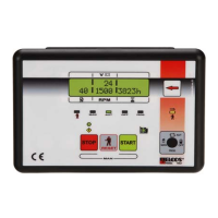
Displays battery voltage, ranging between 9 and 38 Volt.
Shows total operating hours and minutes with five digits, max 59999.
Displays partial operating hours and minutes, four digits, max 9999, resettable.
Counts the number of engine start attempts, up to 9999.
Logs starting failures, counting up to 65535 occurrences.
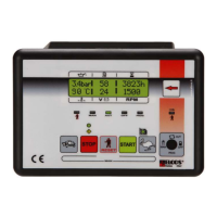
Shows the percentage of fuel remaining in the tank.
Displays engine revolutions per minute, up to 8500 RPM.
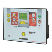
Selects the control unit function via its associated warning light.
Enables control unit commands by pressing the manual key once.
Starts the engine after glow plugs, following call contact closure.
Configures fault display with or without engine stopping.
Automatically runs a test cycle weekly at a programmed time.
Activates preheating in manual or automatically before starting.
Establishes programmable start attempts with pause and run times.
Stops the engine via key press or automatic contact opening.
Produces an acoustic signal, activated continually or for a set time.
Yellow LED flashes indicating maintenance needs and count.
Immediate engine stop via push-button, activating general alarm.
Intervenes if engine running signal is detected 60s after stop command.
Starts engine automatically if battery voltage drops below a set threshold.
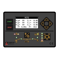
Displays instruments sent via CAN Bus from the engine injection unit.
Indicates anomalies via LED status (red/yellow, steady/flashing).
Details power supply, output terminals, and instrument connections.
Instructions for setting the diverter for pre-excitation alternators.
Wiring for connecting the starter motor and battery terminals.
Diagrams for protection input, fuel float, and output connections.
Steps to enter and navigate the programming operations.
Procedure for setting the correct time and date for logs.
Selectable languages: English, French, German, Spanish, Portuguese.
Enables or disables the automatic weekly test cycle.
Programmes the engine's daily starting consent time range.
Programmes the engine's daily stopping time range.
Advice on connections, interventions, and handling.
Conditions where the control unit is not suitable for operation.
Ensuring correct function within CE marking standards.
Required tasks: check indicators, batteries, and conductor tightness.
Details on power supply, consumption, insulation, and protection.
Type DCA-110 and associated kit MU-DCA-110 ordering codes.
States compliance with electrical and EMC directives and harmonized standards.
| Brand | ELCOS |
|---|---|
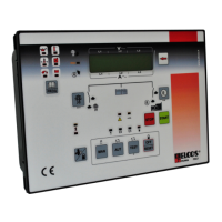
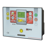
| Model | DCA-110 |
| Category | Control Unit |
| Language | English |